1-11-5
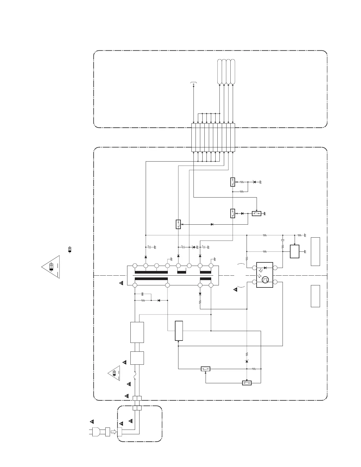
Power Supply Block Diagram
CAUTION !
Fixed voltage (or Auto voltage selectable) power supply circuit is used in this unit.
If Main Fuse (F1000) is blown , check to see that all components in the power supply
circuit are not defective before you connect the AC plug to the AC power supply.
Otherwise it may cause some components in the power supply circuit to fail.
NOTE:
The voltage for parts in hot circuit is measured using
hot GND as a common terminal.
"Ce symbole reprèsente un fusible à fusion rapide."
CAUTION !
For continued protection against fire hazard,
replace only with the same type fuse.
ATTENTION : Pour une protection continue les risqes
d'Incele n'utiliser que des fusible de même type.
Risk of fire-replace fuse as marked.
"This symbol means fast operating fuse."
A V
F
E5WB0BLP
HOT CIRCUIT. BE CAREFUL.
HOT
COLD
8
7
T1001
14
15
18
16
13
12
19
17
LINE
FILTER
L1001
IC1003
IC1011
ERROR
VOLTAGE DET
SHUNT
REG.
D1001-D1004
BRIDGE
RECTIFIER
POWER SUPPLY CBA
3
5
Q1002
Q1001
1
23
4
IC1001
SWITCHING
BD MAIN CBA UNIT
Q1202
F1
F2
FL
+11V
TO SYSTEM
CONTROL
BLOCK
DIAGRAM
PWSW5
CN1004 CN6101
4
11
12
10 16
14
15
22PWSW5
F1
5
6
7
8
9
10
21
20
19
18
17
16
+11V
+11V
+11V
+11V
+11V
+11V
F2
FL
Q1201
Q1203
Q1204
CN1000
1
2
X15
AC CORD
AC1001
CN1002
INLET CBA
1
2
F1000
2.5A/250V
A V
F

 Loading...