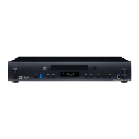
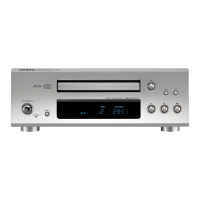
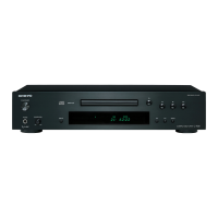
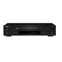
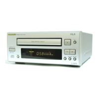
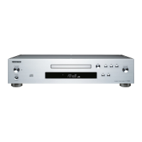
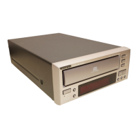
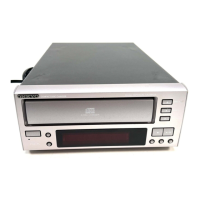
EasyManua.ls Logo

Onkyo C-S5VL

Onkyo C-S5VL
70 pages
To Next Page IconTo Next Page
Loading...
C-S5VL
SERVICE MANUAL
SERVICE MANUAL
SUPER AUDIO CD / CD PLAYER
Black and Silver models
MODEL C-S5VL
120V AC, 60Hz
100-240V AC, 50/60Hz
BMDC
SMUP
BMUP
SMUF
SMUR
Ref. No. 4147
062009
RC-749C
SAFETY-RELATED COMPONENT
WARNING!!
COMPONENTS IDENTIFIED BY MARK ON THE
SCHEMATIC DIAGRAM AND IN THE PARTS LIST ARE
CRITICAL FOR RISK OF FIRE AND ELECTRIC SHOCK.
REPLACE THESE COMPONENTS WITH ONKYO
PARTS WHOSE PART NUMBERS APPEAR AS SHOWN
IN THIS MANUAL.
MAKE LEAKAGE-CURRENT OR RESISTANCE
MEASUREMENTS TO DETERMINE THAT EXPOSED
PARTS ARE ACCEPTABLY INSULATED FROM THE
SUPPLY CIRCUIT BEFORE RETURNING THE
APPLIANCE TO THE CUSTOMER.

Other manuals for Onkyo C-S5VL

Questions and Answers:

Onkyo C-S5VL Specifications

General IconGeneral
Frequency range4 - 50000 Hz
Audio formats supportedMP3, WMA
Total Harmonic Distortion (THD)0.0025 %
Built-in speaker(s)No
CD-RW playbackYes
Device typeHiFi CD player
Product colorSilver
Disc loading typeTray
Number of optical discs1 discs
Volume controlRotary
Headphone outputs1
Power consumption (typical)16 W
Package depth448 mm
Package width562 mm
Package height212 mm
Package weight7000 g
Weight and Dimensions IconWeight and Dimensions
Depth318 mm
Width435 mm
Height80 mm
Weight4500 g

Summary

ONKYO C-S5 VL Product Overview and Safety

Safety-Related Component Warning

Critical components identified by mark are vital for fire and shock protection.

Service Procedures and Precautions

Laser Beam Protection During Servicing

Guidelines for safely servicing the laser pickup block to avoid eye exposure.

General Servicing Precautions

Essential precautions for safe and effective servicing, including grounding.

Fuse Replacement and Version Check

Instructions for fuse replacement, pre-shipment settings, and microprocessor version check.

Firmware Update Process

Confirming and Writing Firmware

Steps to confirm the current firmware version and write new firmware via CD-R.

System Diagrams and Schematics

Exploded View Diagrams

Illustrative diagrams showing the internal components and their assembly.

Block Diagrams

Overall functional block diagram illustrating system interconnections.

Schematic Diagrams

Detailed electrical circuit schematics for various sections of the unit.

Printed Circuit Board Layouts

Visual representations of component placement on various PC boards.

Integrated Circuit Terminal Descriptions

WM8742 DAC IC Details

Block diagram and terminal description for the WM8742 DAC integrated circuit.

System Micon and Display Micon ICs

Terminal descriptions for the main System Micon and Display Micon processors.

Operational Amplifiers and Support ICs

Details for operational amplifiers, voltage regulators, and other support ICs.

Parts List and Packing Information

Packing Procedure

Illustrated steps for packing the unit and its accessories for shipment.

Exploded View Parts List

List of all parts with reference numbers, descriptions, and quantities.

Related product manuals