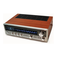
Do you have a question about the Onkyo TX-4500 and is the answer not in the manual?
Adjusting the tuning knob initiates the tuning process, involving amplification and rectification.
Regulates local oscillation frequency by detecting IF and quartz signals, amplifying variance.
Displays tuning accuracy by comparing IF and quartz signal levels, indicating center point.
Operates based on IF carrier, 0-point detection, and noise component for muting control.
Ensures stable power supply to the protection circuit with a time constant for output protection.
Monitors for DC generation at the center line, triggering relay action to cut off output.
Detects abnormal current in the power stage, activating protection to cut off output.
Adjusts output voltage to ±20mV (TX-4500) or ±40mV (TX-2500) at speaker terminals.
Sets idle current to ±5mV at speaker terminals for both models.
Adjusts protection circuit parameters by applying signal to the differentiation circuit.
Aligns the quartz locked circuit using a 10.7MHz sweep generator and monitorscope.
Aligns the servo locked circuit using a 10.7MHz sweep generator and monitorscope.
Aligns the AM IF circuit using a 455KHz sweep generator and monitorscope.
Aligns the AM RF section using signal generators and an AC VTVM.
Aligns the FM front end using FM signal generator and monitorscope.
Aligns FM mono distortion and multiplex sections using stereo modulator and distortion analyzer.
Adjusts FM tuning meter, strength meter, and muting level using signal generator and VTVM.
Details the procedure for threading the dial cord around pulleys for tuning display.
Details the procedure for threading the dial cord around pulleys for tuning display.
Explains how to release a binder mechanism using a driver or pin.
Describes when to switch the sensor to HIGH position for improved sensitivity.
Details the method for removing the tuning knob using a hexagonal driver.
Lists parts for the FM/AM PC board (NAIMX-345) of the TX-2500.
| Tuning Range | FM, MW |
|---|---|
| Input Sensitivity | 2.5 mV (MM), 150 mV (line) |
| Output | 150 mV (line) |
| Power Output | 60 watts per channel (8 ohms, 20Hz-20kHz, 0.08% THD) |
| Total Harmonic Distortion | 0.1% |
| Signal to Noise Ratio | 90 dB (line) |
| Damping Factor | 40 |
| Speaker Load Impedance | 4Ω to 16Ω |
| Frequency Response | 10Hz-50kHz (+0.5dB, -1dB) |