EasyManua.ls Logo

Onkyo TX-7620 - Page 7

Onkyo TX-7620
19 pages
Print Icon
To Next Page IconTo Next Page
To Previous Page IconTo Previous Page
Loading...
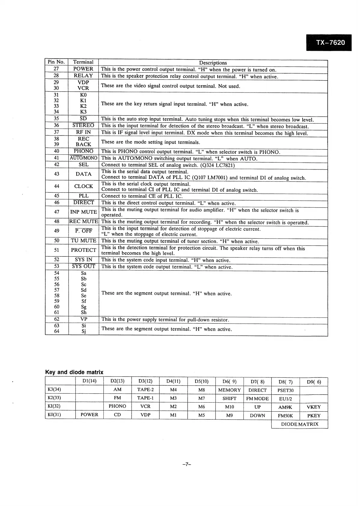
TX-—7620
Pin
No.
Descriptions
POWER
|
Pin
No.
|
|
27.
|
POWER
|
This
is
the
power
control
output
terminal.
“H”
when
the
power
is
turned
on.
This
is
the
speaker
protection
relay
control
output
terminal.
“H”
when
active.
31
KO
2
as
These
are
the
key
return
signal
input
terminal.
“H”
when
active.
33
K2
|
y
a
34
K3
This
is
the
auto stop
input
terminal.
Auto
tuning
stops
when
this
terminal
becomes
low
level.
STEREO
|
This
is
the
input
terminal
for
detection
of
the
stereo
broadcast.
“L”
when
stereo
broadcast.
37
RF
IN
This
is
IF
signal
level
input
terminal.
DX
mode
when
this
terminal
becomes
the
high
level.
These
are
the
mode
setting
input
terminals.
|
PHONO
|
This
is
PHONO
control
output
terminal.
“L”
when
selector
switch
is
PHONO.
AUTO/MONO
|
This
is
AUTO/MONDO
switching
output
terminal.
“L”
when
AUTO.
Connect
to
terminal
SEL
of
analog
switch.
(Q324
LC7821)
PLL
3
4
4
Loe)
oe)
om
or
res
a")
an
O
Z
O
DATA
This
is
the
serial
data
output
terminal.
Connect
to
terminal
DATA
of
PLL
IC
(Q107
LM7001)
and
terminal
DI
of
analog
switch.
CLOCK
This
is
the
serial
clock
output
terminal.
Connect
to
terminal
CI
of
PLL
IC
and
terminal
DI
of
analog
switch.
Connect
to
terminal
CE
of
PLL
IC.
DIRECT
|
This
is
the
direct
control
output
terminal.
“L”
when
active.
INP
MUTE
pn
ae
muting
Output
terminal
for
audio
amplifier.
“H”
when
the
selector
switch
is
REC
MUTE;
This
is
the
muting
output
terminal
for
recording.
“H”
when
the
selector
switch
is
operated.
This
is
the
input
terminal
for
detection
of
stoppage
of
electric
current.
P,
OFF
66 99
e
L”
when
the
stoppage
of
electric
current.
TU
MUTE
|
This
is
the
muting
output
terminal
of
tuner
section.
“H”
when
active.
PROTECT
This
is
the
detection
terminal
for
protection
circuit.
The
speaker
relay
turns
off
when
this
terminal
becomes
the
high
level.
SYS
IN
|
This
is
the
system
code
input
terminal.
“H”
when
active.
SYS
OUT
|
This
is
the
system
code
output
terminal.
“L”
when
active.
9
0
1
2
3
4
5
6
7
8
9
4
4
4
4
4
4
4
4
50
51
52
These
are
the
segment
output
terminal.
“H”
when
active.
This
is
the
power
supply
terminal
for
pull-down
resistor.
These
are
the
segment
output
terminal.
“H”
when
active.
Key
and
diode
matrix
Cf
ie)
ree
fea)
SFT
70
D9
6)