EasyManua.ls Logo

Onkyo TX-910 Service Manual

Onkyo TX-910
31 pages
To Next Page IconTo Next Page
Page #1 background imageLoading...
Page #1 background image
Ref.
No.
3443
ONXYO
SERVICE
MANUAL
QUARTZ SYNTHESIZED
TUNER AMPLIFIER
MODEL
TX-9
10
MODEL
TX-930
Black and Silver models
1
BHMD, BHMDN
1
120V AC, 60Hz
1
BHMP, BHMPF, MP, MPF
1
23OV
AC,
50Hz
1
l20V
or
220l AC iO/6OHz
1
SAFETY-RELATED COMPONENT WARNING!
!
COMPONENTS IDENTIFIED BY MARK
d
ON
THE SCHEMATIC DIAGRAM AND IN THE PARTS
LIST ARE CRITICAL FOR RISK OF FIRE AND
ELECTRIC SHOCK. REPLACE THESE COMPO-
NENTS WITH ONKYO PARTS WHOSE PART
NUMBERS APPEAR AS SHOWN IN THIS
MANUAL.
BHMQA
MAKE LEAKAGE-CURRENT OR RESISTANCE
MEASUREMENTS TO DETERMINE THAT EXPOSED
PARTS ARE ACCEPTABLY INSULATED FROM
THE SUPPLY CIRCUIT BEFORE RETURNING
THE APPLIANCE TO THE CUSTOMER.
240V AC, 50Hz
I
ONKYO
I
TABLE
OF
CONTENTS
Printed circuit board view from bottom side
...................
23
Schematic diagram
~~d~l TX-930
..........................................................
7-
,
D
Model TX.910
..........................................................
2
9
Printed circuit board-parts list
~~d~l ~x.930
..........................................................
35
Model TX.910
..........................................................
38

Other manuals for Onkyo TX-910

Question and Answer IconNeed help?

Do you have a question about the Onkyo TX-910 and is the answer not in the manual?

Onkyo TX-910 Specifications

General IconGeneral
Input Sensitivity2.5 mV (MM), 150 mV (line)
Tuning rangeFM, MW
Total Harmonic Distortion0.08%
Frequency Response20Hz to 30kHz
Speaker load impedance8 ohms (minimum)

Summary

Specifications

Amplifier Section

Details power output, distortion, damping factor, and frequency response for amplifier performance.

Tuner Section

Covers FM and AM tuning range, sensitivity, signal-to-noise ratio, and distortion.

General

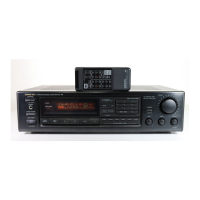
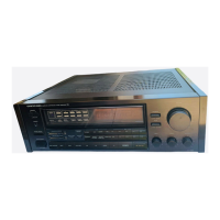
Provides overall dimensions and weight specifications for the models.

Service Procedures

Fuse Replacement and Safety Checks

Instructions for fuse replacement and safety insulation resistance testing.

Voltage and Band Setting Adjustments

Covers changing voltage selectors and band step selectors for regional compatibility.

Memory Preservation

Explains the unit's power-back-up system for memory contents during power failures.

Exploded View TX-930

Parts List TX-930

Exploded View TX-910

Parts List TX-910

Block Diagram TX-930

Block Diagram TX-910

IC Block Diagram LM7001

IC Block Diagram μPD17103CX

IC Block Diagram μPD75268CW-025

LA1266 FM/AM Radio System

AN7470 Stereo Decoder

Block diagram and function for the AN7470 stereo decoder IC.

LB1630 Motor Driver

Block diagram and truth table for the LB1630 motor driver IC.

FIP9BTM8 Fluorescent Tube

LC7823/LC7823N Analog Switch

μPC1225H Power Amplifier Driver

NJM4558D-X Operation Amplifier

Packing View

Adjustment Procedures

Preparation and Standard Knob Positions

Outlines initial setup steps, required inputs, outputs, and standard knob settings.

Operation Confirmation

Details checks for protection circuit operation, speaker relay, and over-voltage confirmation.

Amplifier Section Idling Current Adjustment

Procedure for adjusting the idling current for the amplifier section using specific resistors.

Adjustment Procedures - FM/AM Sections

FM Section Adjustments

Step-by-step guide for adjusting FM IF, VCO, Stereo, and Tuned indicator levels.

AM Section Adjustments

Procedures for adjusting AM SG output, RF coil, and muting levels.

Printed Circuit Board Parts List TX-930

Printed Circuit Board Parts List TX-930

Printed Circuit Board Parts List TX-930

Printed Circuit Board Parts List TX-930

Printed Circuit Board Parts List TX-910

Printed Circuit Board Parts List TX-910

Printed Circuit Board Parts List TX-910

Related product manuals