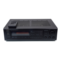
Remote control transmitter
RC-223s
Transmitter: Infrared
S~gnal range: Approx.
5
meters (16ft.
X
4"
)
Power supply: Two
'AA'
batterles(l.5V
X
2)
Spec~f~cat~ons and features are subject to change without notice.
SERVICE PROCEDURES
1.Replacing the fuses
For
continuad protec~n
against
fire
hazard,rcplace
only
with
same
type
and
same
rating
fuse.
Ciuit
No. Pan No. Description
Model
Type
F901 252049 4A(STd)Srimary TX-910
MDMW
F901 252050 5A(ST-6)Snmary TX-930
MDMW
F902
252073 ~M-SE-EAK.R~IMIY TX-910
MP/MWMQ
F902 252075 25A-SE-EAKSnmary TX-930
MP/MWMQ
F951 252074 22-SE-EAKbC
outlet
TX-930
MP
2.Safety-check out
(Only U.S.A. model)
After correcting the original service
problem.perform
the following safety check before releasing the set to
the customer.
Connect the insulating-resistance tester between the
plug of power suuply cord and nickel screw on the back
panel.
Specifications:
3.3Mohm
t
10% at 500V.
%Change of voltage
Worldwide models are equipped with a voltage selector to
conform with local power supplies. This switch is located
on the back panel. Be sure to set this switch to match
the voltage of the power supply in your area before
turning the power switch on.
This swith is set to 220V at the factory. Voltage is
changed by sliding the groove in the switch with the
screwdriver to the right or left. Confirm that the switch
has been moved all the way to the right or left before
turning the power switch on.
4.Step band selector switch
Worldwide models are equipped with a step band selector
switch. This switch is located on the back panel. This
switch is set to
50kHz (FM) and 9kHz (AM) at the factory,
but may have to be reset to
lOOkHz and lOkHz depending on
the area where the unit is used.
De-emphasis FM step AM step
Europe:
50psec 50kHz 9kHz
U.S.A.: 75psec ZOOkHz lOkHz
5.Changing
the
band
step
With the exception of the models below, a
BAND
STEP
selector switch is not provided.
Shorted
Refer
to
thepage23.
c
MODEL
UD
UPAJQ
Q701
MICROPROCESSOR
l$l~lg
4
6.Memroy preservation
This unit does not require memory preservation batteries.
A built-in memory power back-up system preserves contents
of the memory during power failures and even when the
unit is unplugged. The unit must be plugged in and the
power switch turned on and off once
m
order to charge the
back-up system. Note that since this is not a permanent
memory,the power switch must be turned on and off a few
times each month to keep the back-up system operative.
The period of time during which memory contents are
preserved after power has last been turned off varies
depending on climate and
placement of the unit.
On the average, memory contents are protected over a
period of
3
to
4
weeks (a minimum of
2
weeks) after
the last time power has been turned off. This period is
shorter when the unit is exposed to very high humidity or
used in an area with an extremely humid climate.
BAND
STEP
1OkHz-+9kHz
9&-lOkHz
R709(10kSZ)
Add
J732
Shorted
Cut

 Loading...