Chapter 4: Modules
16 HOBO Energy Logger Pro User’s Guide
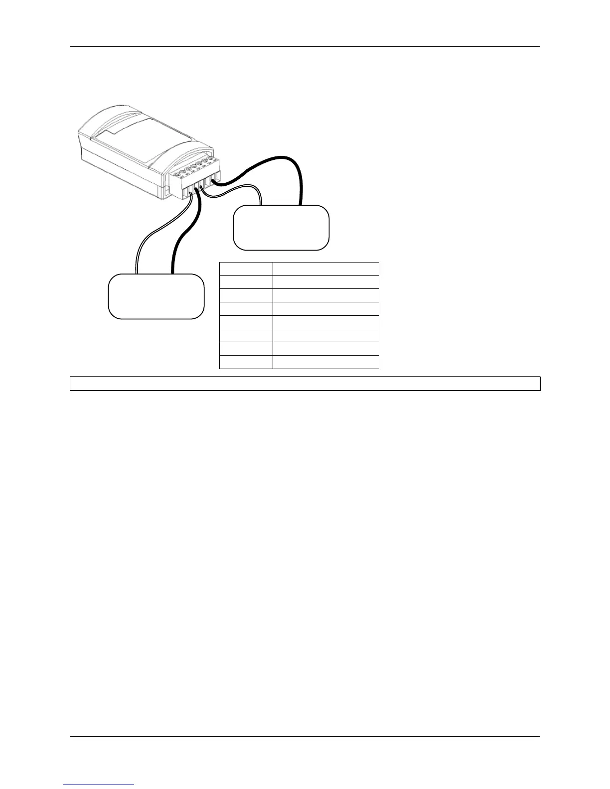
The following example illustrates typical connections for a voltage sensor, and a current sensor that requires
excitation:
1
2
3
4
5
6
7
4 - 20 mA
Transducer
Excitation
IN
Pin #
1
2
3
4
5
6
7
Function
Shield
Channel 1 Input
Channel 1 Return
Excitation Voltage
Excitation Return
Channel 2 Input
Channel 2 Return
Signal
OUT
0 - 5 Volt
Transducer
Signal
OUT
Signal
GRND
Tip: Always refer to your sensor documentation for terminal connection details.
Once the sensors are connected, install the Analog module into any of the three module slots on the logger. For more
information, refer to “Assembling the logger” on p. 4.
Use the provided label to identify a module/sensor combination to aid in determining sensor placement and cable
routing when in the field.
Configuring channels
Each channel of the Analog module is individually configurable to accept a wide range of sensors. That means that
each channel can be configured to measure either current or voltage, and the collected data can be scaled to produce
meaningful results that are consistent with the properties being measured.
Use HOBOware Pro to configure each channel at launch time, or create and save different configurations to be
loaded into the modules whenever needed. A channel configuration consists of a channel name, measured property
name, scaling parameters, and excitation information, if applicable. Refer to the HOBOware Pro User’s Guide for
details.
Verifying operation
The Analog module begins functioning when logging begins. When the module is functioning correctly, the
Active
indicator on the module blinks once per logging interval for each configured channel to indicate that a successful
measurement has been made.