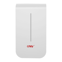
The PoE port of the POE power supply is connected to the WAN port of the outdoor
CPE through a network cable, and the powe r supply is plugged into the socket to
supply power to the CPE through the network cable. Note that the POE power supply
needs to match the voltage and current supported by the CPE. Here the power supply
support 24V 0.5A/1A (model: CPE300) or 48V 0.45 A/0.6A (model: CPE300P).
POE power supply mode
Use POE power module to supply power
Wireless AP interface
Move switch
4.Digital display bridge
1. The default digital display of the device is 0. Short press the Reset button to
switch the digital display.
2. The default switch of the device is AP mode (right), slide the switch to the right to
save the digital display number.
3. Turn the two devices into AP mode (right) and client mode (left) respectively,
and the devices will be paired automatically.
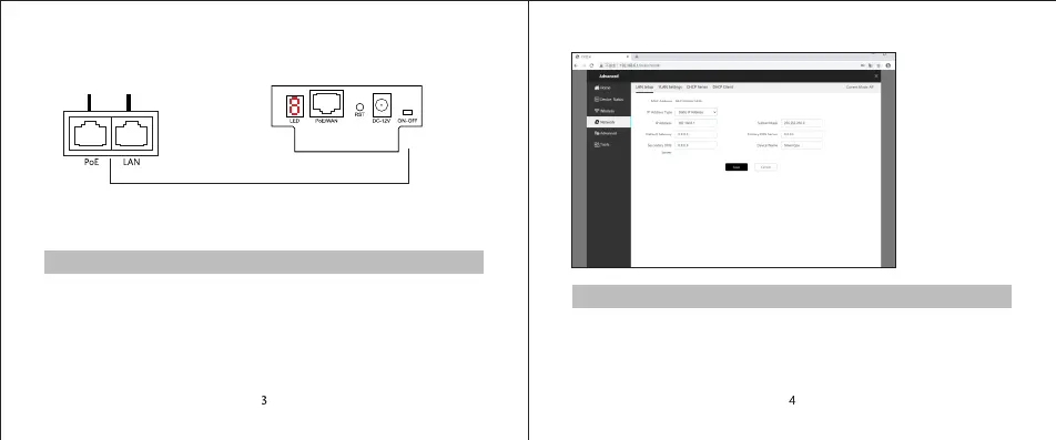
4. After the pairing is successful, the IP of AP mode (right) is: 192.168.6.1, and the
IP of client mode (left) is issued by the AP, as shown in the following figure.
5.Log in to the CPE system
CPE management page login default IP address:
192.168.6.1 account/password: adminThe login
interface can be switched between Chinese and English.