USE AND MAINTENANCE INSTRUCTIONS
MANUALE DI USO E MANUTENZIONE
34
Transom gangway
Passerella esterna
EDITION OF 08/2008
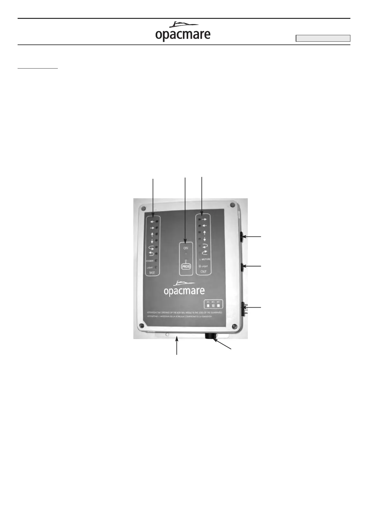
Electrical panel (picture 20) / Quadro elettrico (fig. 20)
ã COMMAND DESCRIPTION:
Electrical box
The electrical panel, housed inside a box that is waterproof to
1P65 standards, is usually installed in the engine room.
The box is secured with the two side flaps
A provided.
The power cables enter the box through the cable clamp B, and
the electronic circuit board is protected by fuse C.
The pre-wired solenoid valves must be connected to socket
D.
The control panel connector must be inserted into socket E.
On the cover of the electrical panel there are indicator lights to
show the status of inputs F , sensor G and end-of-travel sensors.
These lights are important for rapid fault-fincling in case of malfun-
ctions. The “PROG” button
H allows any remote-control units to
be programmed as described in the next section
ã DESCRIZIONE DEI COMANDI:
Quadro elettrico
Il quadro elettrico, contenuto in una scatola IP65 viene di norma
collocato all’interno dei locale motori.
La scatola viene fissata tramite le due alette laterali
A, l’alimenta-
zione è collegata al connettore B e la scheda elettronica è protet-
ta da un fusibile
C. Il collegamento delle elettrovalvole viene effet-
tuato sulla presa D, il connettore del pannello dei comandi viene
inserito nella presa E. Sul coperchio del quadro elettrico si trova-
no le spie con lo stato degli ingressi F, delle uscite G, importanti
per una rapida ricerca in caso di malfunzionamenti. Il tasto ‘PROG’
H, permette la codifica dei radiocomandi secondo le modalità
descritte nel paragrafo seguente.
F
D
C
A
E
B
H
G