Installation, important notes!
- Excessive heat development from be-
low, e.g. from a baking oven without
cross-flow fan, should be avoided.
- If pyrolysis operation takes place at
built-in cookers, the induction hob
must not be used.
- When installing above a drawer, care
must be taken to ensure that no
sharp objects are stored in the dra-
wer. These could tilt on the underside
of the hob and block the drawer.
- If there is an interm
ediate bottom be-
low the hob, sufficient ventilation of
the hob inductors must be ensured.
- The cooktop must not be installed
above refrigerators, dishwashers,
washing machines or dryers.
- It must be ensured that no flammable,
easily flammable or heat deformable
objects are placed directly next to or
below the hob due to the risk of fire.
Hob gasket
Wood worktops must be sealed on the
cut surfaces.
Before installation, the enclosed
cooktop
gasket must be inserted without gaps.
- It must be prevented that liquids can
penetrate between the edge of the hob
and the worktop or between the worktop
and the wall into any electrical appli-
ances installed underneath.
- If the hob is installed in an uneven
worktop, e.g. with a ceramic or similar
covering (tiles, etc.), the cooking surface
must be sealed against the worktop with
plastic sealing materials (e.g. Novasil®
or Ottoseal® ).
Note:
- If sealing adhesive is used for sealing
and fixing, a later, non-destructive re-
moval of the hob cannot be guaranteed.
Worktop cut-out
The cut-out in the worktop should be
made as accurately as possible with a
good, straight saw blade or a router.
The cut surfaces should then be sealed
to prevent moisture from penetrating.
The cut-out for the ho
b is made accord-
ing to the illustrations. The glass-
ceramic hob surface must be flat and
flu
sh. Tensioning can cause the glass
plate to break. Check the seal of the
cooking surface for a perfect fit and
complete support.
Exhaust air - outlet opening
The cross-section of the wall boxes and
the cut-out in the plinth panels should at
least correspond to the exhaust air ope-
ning. There must be one or more air
outlet openings of at least 500cm² in
total.
Shorten the height of the skirting
boards or insert corresponding ope-
nings.
> 500mm²
EN
17
WARNING AGAINST ELECTRICAL ENERGY! THERE IS DANGER TO LIFE!
• There are voltage-carrying parts near this symbol.
• Covers marked with this symbol may only be removed by a qualified electrician.
• The electrical connection may only be carried out by an authorised specialist!
• The statutory regulations and connection conditions of the local electrical supply company must be
observed in full.
• When the device is connected, a device must be provided which makes it possible to disconnect the
device from the mains with an opening width of at least 3 mm all poles using a contact. LS switches,
fuses and contactors are regarded as suitable disconnecting devices. When connecting and
repairing the device, disconnect it from the power supply using one of these devices.
• The protective conductor must be long enough so that if the strain relief fails, it will only be subjected
to tensile stress after the current-carrying cores of the connecting cable.
• The excess cable length must be pulled out of the installation area below the device.
• Please make sure that the mains voltage is the same as on the nameplate.
• Complete protection against accidental contact must be ensured by installation.
• Attention: Incorrect connection can lead to destruction of the power electronics.
• The device is only approved for a fixed connection. It must not be connected with a shock-proof plug.
Connected loads
Mains voltage: 380-415 V 3N~, 50/60 Hz
Connecting cable available at the factory
• The hob is equipped with a temperature-resistant connection cable at the factory.
• The mains connection is carried out according to the connection diagram, except the connection
cable is already equipped with a plug.
• If the power cord of this unit is damaged, it must be replaced with a special power cord. In order to
avoid hazards, this may only be done by the manufacturer or his customer service.
Black
Brown
Blue
N
L1
Green/Yellow
L2
L3
Three phase connection:
3N 380-415 V 50/60 Hz 5x1.5 mm²
Gray
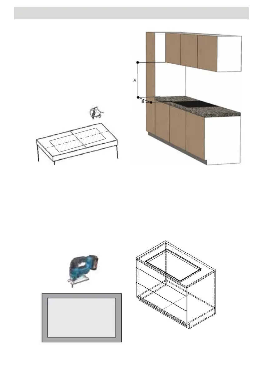
Note: Minimum distances should be maintained.
"A" hob - upper cabinet > 600 mm
"B" hob - side cabinet > 300mm
To avoid water steam damage, we recommend
placing a panel behind the wall cupboards.
This will prevent accumulation of moisture between
the cabinets.
1. Remove the front or drawers
2. Define and mark the positions forthe cut-out on the kitchen worktop. Please pay attention to
minimum distances and minimum web width ! These may vary depending on the material and
material properties! (Under certain circumstances use auxiliary crossbar "Reinforcement").
3. Saw out the cut -out on the worktop. Pay attention to straightness and freedom from burrs ! For "�
ush installation", mill out the recess.
4. Seal milled surfaces
5. If necessary, make cut -outs in the base cabinet �oor and plinth.
6. Adjust rear drawer panels if necessary.
7. PU sealing tape 3x10 mm at the mount bearing surfaces all around. Flush mounting also possible in
the countersink. Consider the height of the glass plate. Level adjustment if required.
8. Installation instructions for OPERA hobs with downdraft fan. If the underlay has to be carried out, this
underlay must be carried out evenly according to the specification below.ù Milling must be checked
for evenness after assembly of the worktop . ! We accept no liability for incorrectly placed hobs !
Insert 12x shims in the hob cut-out according to the dimensions
9. Remove the furniture drawers or remove the front of the kitchen unit.
10. Check base cut-out for dimensions and flatness and adjust if necessary
11. Unscrew the handle and outlet nozzle of the Nivel Professional.
12. Insert the Nivel Professional hob extractor. Make sure that the seal is
placed properly. Observe and compensate for height di�erences. Here
the highest caution is required - danger of breakage !
13. Align the hob, fill the joint (e.g. Novasil® or Ottoseal®) and smooth.
14. Create duct connection. If the silencers are installed, then also the height of the intake silencer must
be considered when measuring X.
Note: Minimum distances should be maintained.
"A" hob - upper cabinet > 600 mm
"B" hob - side cabinet > 300mm
To avoid water steam damage, we recommend
placing a panel behind the wall cupboards.
This will prevent accumulation of moisture between
the cabinets.
1. Remove the front or drawers
2. Define and mark the positions forthe cut-out on the kitchen worktop. Please pay attention to
minimum distances and minimum web width ! These may vary depending on the material and
material properties! (Under certain circumstances use auxiliary crossbar "Reinforcement").
3. Saw out the cut -out on the worktop. Pay attention to straightness and freedom from burrs ! For "�
ush installation", mill out the recess.
4. Seal milled surfaces
5. If necessary, make cut -outs in the base cabinet �oor and plinth.
6. Adjust rear drawer panels if necessary.
1. Determine and mark the positions for the cut-out on the kitchen worktop. Please
pay attention to minimum distances and minimum web widths! These may vary de-
pending on the material and material properties!
(Under certain circumstances, use auxiliary crossbars).
2. Make a cut-out at the worktop. Pay
attention to straightness and freedom
from burrs !
Note : Minimum distances
"A" hob - upper cabinet > 600 mm
"B" hob - side cabinet > 300mm
should be maintained.
To avoid water steam damage, we rec-
ommend placing a panel behind the wall
cupboards. This will prevent accumula-
tion of moisture between the cabinets.
EN
19
ASSEMBLY INSTRUCTIONS
Contact closed !
Extractor hood operation possible
only with opended window or
supply air duct
Contact opened !
Extractor hood operation
deactivated with closed window
or no supply air duct.
The hood touch control blinks
Please note that your gas boiler or open fireplace will produce exhaust gases through
convection of the heated exhaust air from your living spaces to the outside.
Your exhaust fume extraction works by forced convection and therefore causes
a negative pressure in the living space, which sucks in the exhaust gases and/or the
exhaust gases of their house co-inh
abitants from the chimney brings back.
Functional description:
The control of your OPERA cooker hood is equipped with a window contact circuit. If
the contact loop of the controller is interrupted, the power supply to the fan motor is
interrupted. The OPERA cooker hood lighting continues to function.
The window contact is mandatory in Germany.
Only window contact switches approved by DIBt (Deutsches Institut für
Bautechnik) may be connected potential-free to the contact loop.
The contact must be closed when the window is open!
( pressure switch not actuated = closed ) ( reed switch open in magnetic field )
For detailed wiring options, please refer to the window contact brochure request.
EN
30
10. CONTACT WITH WINDOW SWITCH (exhaust air operation)
7. PU sealing tape 3x10 mm at the mount bearing surfaces all around. Flush mounting also possible in
the countersink. Consider the height of the glass plate. Level adjustment if required.
8. Installation instructions for OPERA hobs with downdraft fan. If the underlay has to be carried out, this
underlay must be carried out evenly according to the specification below.ù Milling must be checked
for evenness after assembly of the worktop . ! We accept no liability for incorrectly placed hobs !
Insert 12x shims in the hob cut-out according to the dimensions
9. Remove the furniture drawers or remove the front of the kitchen unit.
10. Check base cut-out for dimensions and flatness and adjust if necessary
11. Unscrew the handle and outlet nozzle of the Nivel Professional.
12. Insert the Nivel Professional hob extractor. Make sure that the seal is
placed properly. Observe and compensate for height di�erences. Here
the highest caution is required - danger of breakage !
13. Align the hob, fill the joint (e.g. Novasil® or Ottoseal®) and smooth.
14. Create duct connection. If the silencers are installed, then also the height of the intake silencer must
be considered when measuring X.
55
FITTING INSTRUCTIONS EN
 Loading...