Note: Minimum distances should be maintained.
"A" hob - upper cabinet > 600 mm
"B" hob - side cabinet > 300mm
To avoid water steam damage, we recommend
placing a panel behind the wall cupboards.
This will prevent accumulation of moisture between
the cabinets.
1. Remove the front or drawers
2. Define and mark the positions forthe cut-out on the kitchen worktop. Please pay attention to
minimum distances and minimum web width ! These may vary depending on the material and
material properties! (Under certain circumstances use auxiliary crossbar "Reinforcement").
3. Saw out the cut -out on the worktop. Pay attention to straightness and freedom from burrs ! For "�
ush installation", mill out the recess.
4. Seal milled surfaces
5. If necessary, make cut -outs in the base cabinet �oor and plinth.
6. Adjust rear drawer panels if necessary.
4. Installation instructions for OPERA hobs with downdraft fan
If the underlay has to be carried out, this underlay must be carried out evenly
according to the specification below.
Milling must be checked for evenness after assembly of the worktop .
! We accept no liability for incorrectly placed hobs !
Insert 12x shims in the
hob cut-out according to
the dimensions
3. PU sealing tape at the mount bearing surfaces all around.
Flush mounting also possible in the countersink. Consider the height of
the glass plate. Level adjustment if required.
underlay
EN
21
Contact closed !
Extractor hood operation possible
only with opended window or
supply air duct
Contact opened !
Extractor hood operation
deactivated with closed window
or no supply air duct.
The hood touch control blinks
Please note that your gas boiler or open fireplace will produce exhaust gases through
convection of the heated exhaust air from your living spaces to the outside.
Your exhaust fume extraction works by forced convection and therefore causes
a negative pressure in the living space, which sucks in the exhaust gases and/or the
exhaust gases of their house co-inh
abitants from the chimney brings back.
Functional description:
The control of your OPERA cooker hood is equipped with a window contact circuit. If
the contact loop of the controller is interrupted, the power supply to the fan motor is
interrupted. The OPERA cooker hood lighting continues to function.
The window contact is mandatory in Germany.
Only window contact switches approved by DIBt (Deutsches Institut für
Bautechnik) may be connected potential-free to the contact loop.
The contact must be closed when the window is open!
( pressure switch not actuated = closed ) ( reed switch open in magnetic field )
For detailed wiring options, please refer to the window contact brochure request.
EN
30
10. CONTACT WITH WINDOW SWITCH (exhaust air operation)
Connection to the control board of the cooker hood:
As shown in the illustration, the connection cable is fixed to the unit surface with a
label. For direct connection of a pressure switch or
Reed switch on the cooker hood must open when the window is closed.
Use only potential-free
window contact switches.
Attention:
Please observe the instructions on the first page and have the
execution confirmed by the specialist company after the
installation has been completed !
EN
31
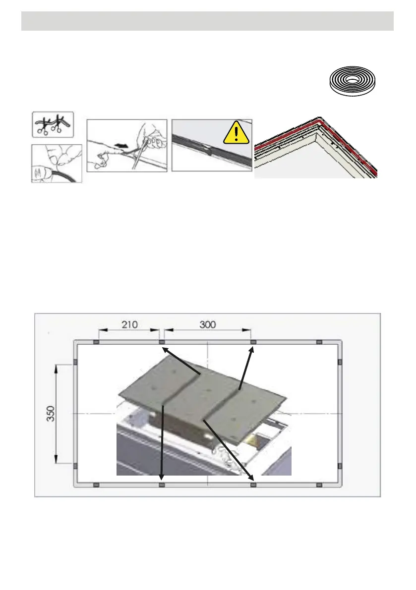
7. PU sealing tape 3x10 mm at the mount bearing surfaces all around. Flush mounting also possible in
the countersink. Consider the height of the glass plate. Level adjustment if required.
8. Installation instructions for OPERA hobs with downdraft fan. If the underlay has to be carried out, this
underlay must be carried out evenly according to the specification below.ù Milling must be checked
for evenness after assembly of the worktop . ! We accept no liability for incorrectly placed hobs !
Insert 12x shims in the hob cut-out according to the dimensions
20
8. Installation instructions for OPERA hobs with downdraft fan
If the underlay has to be carried out, this underlay must be carried out evenly
according to the specification below.
Milling must be checked for evenness after assembly of the worktop .
! We accept no liability for incorrectly placed hobs !
Insert 12x shims in the
hob cut-out according to
the dimensions
7. PU sealing tape 3x10 mm at the mount bearing surfaces all around.
Flush mounting also possible in the countersink. Consider the height of
the glass plate. Level adjustment if required.
underlay
9. Remove the furniture drawers or remove the front of the kitchen unit.
10. Check base cut-out for dimensions and flatness and adjust if necessary
11. Unscrew the handle and outlet nozzle of the Nivel Professional.
12. Insert the Nivel Professional hob extractor. Make sure that the seal is
placed properly. Observe and compensate for height di�erences. Here
the highest caution is required - danger of breakage !
13. Align the hob, fill the joint (e.g. Novasil® or Ottoseal®) and smooth.
14. Create duct connection. If the silencers are installed, then also the height of the intake silencer must
be considered when measuring X.
56
FITTING INSTRUCTIONSEN
 Loading...