Fire Protection | Data sheet No. 41300 | Version 06-2012 | 5 | 9
Duct Smoke Detector KRM
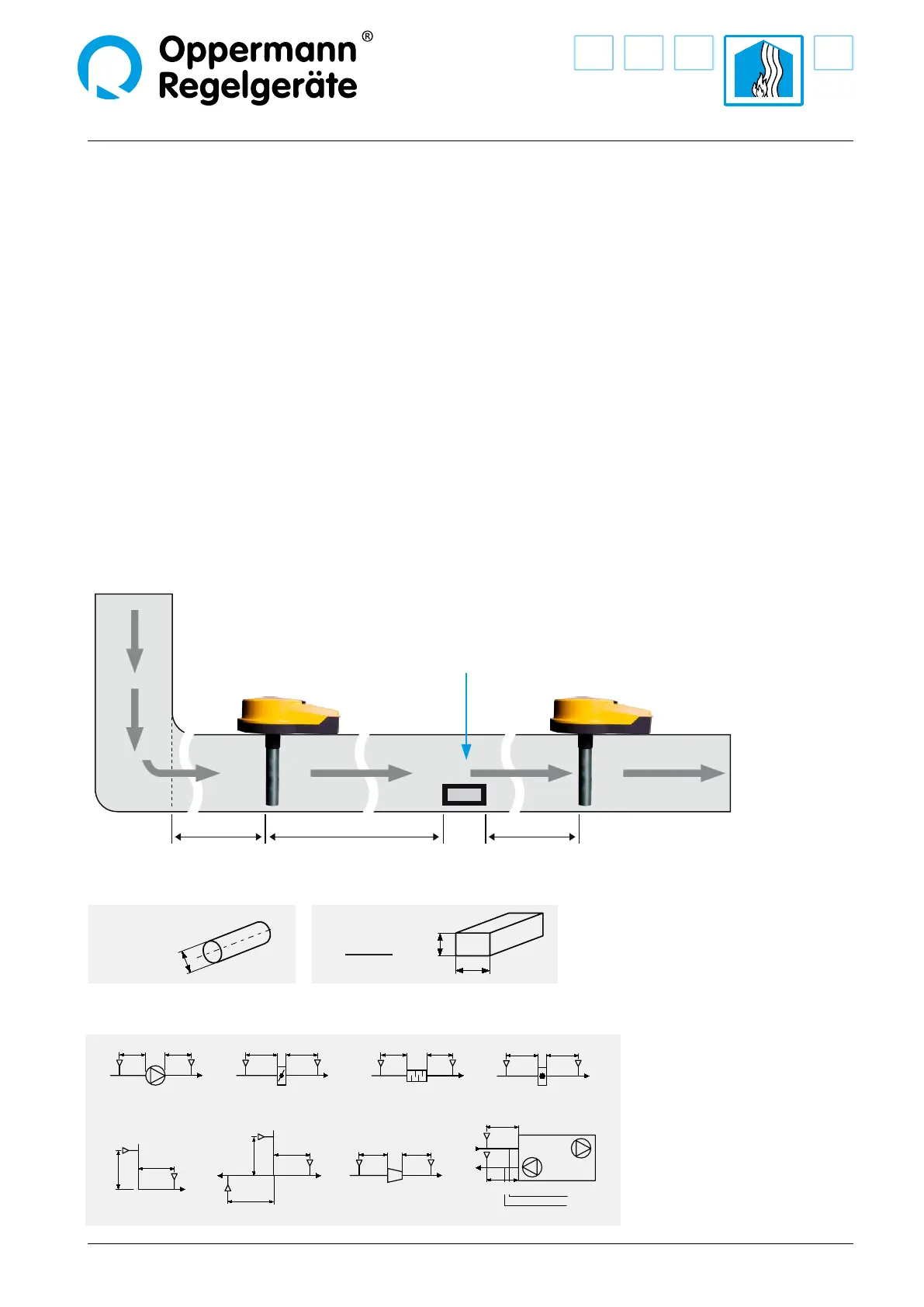
In the ideal case, install the KRM when structurally possible,
where ow meters, etc. are normally attached, so there is a lami-
nar airow along the measuring tube. We recommend that the
KRM be tted and installed at the same distance from heating,
cooling and humidity devices as ow sensors. The distance of
the KRM to ttings, valves, lters, etc. in terms of ow direc-
tion should be 3 times, and in the diagonal direction 5 times
that of the cross-section, if this structurally possible. The KRM
including the air collecting tube may not be installed along the
longitudinal edges of ventilation ducts (corner area). The KRM
is to be installed so that the air collecting tube is constantly in
the air stream. In horizontal ventilation ducts the KRM including
air collecting tube should be installed in the upper third of the
ventilation ducts or at the top of the ventilation ducts, if this is
structurally possible.
When, for structural reasons, the recommended positioning is
not possible, the KRM is to be mounted so that, nonetheless, a
reliable smoke detection/ow is ensured. The blue LED “Airow”
may be used as an indicator of a sucient ow (the LED is o
with sucient ow).
Follow these instructions. All work (such as installation, electri-
cal connection, start-up, operation and maintenance), must
be carried out by suciently qualied craftsman. Current local
rules and regulations (e. g. building regulations, elecrical/VDE
guidelines, etc.) are to be observed. Installers and operators are
required to be adequately informed before operation. Read the
product description before device start-up. Make sure that the
product is fully suited to the respective applications. We assume
no liability for misprints and changes after printing. Compliance
with operating and installation instructions is also included
within the regulations of intended use. We assume no liability
for damages caused by improper use. Operating licenses and
guarantees and all warranty claims will be voided in the event
of unauthorized modications or any tampering with the
device.
Hydraulic diameter d
h
Example of positioning
after the change of
air duct direction. (Recommendation)
Example of positioning
after air outlets. (Recommendation)
Air outlet
Where there are large temperature dierences,
outdoors for example, or in places that are
dependent on outside temperature (roof, attic),
the air duct smoke sensor has to be insulated.
For this Oppermann Regelgeräte provides
a special splash-proof housing (WDG).
5 d
h
3 d
h
5 d
h
MIN 3xd
h
MIN 5xd
h
MIN 3xd
h
MIN 5xd
h
MIN 3xd
h
MIN 5xd
h
MIN 3xd
h
MIN 5xd
h
KRMKRMKRMKRMKRMKRMKRMKRM
KRM
KRM
KRM
KRM
KRM
KRM
KRM
KRM
MIN 5xd
h
MIN 3xd
h
MIN 5xd
h
MIN 5xd
h
MIN 3xd
h
MIN 3xd
h
MIN 5xd
h
MIN 5xd
h
MIN 3xd
h
Exhaust air
Supply air
Ventilator Airap Muer
Battery
Air duct device
Air duct narrowing/
Air duct enlargement
Air duct forking
Change in air
duct direction
d
h
=
2xHxW
H+W
H
W
Rectangular duct
d
h
=D
øD
Round duct
Example of positioning (Recommendation)
 Loading...