ENGLISH FRANÇAIS DEUTSCH ITALIANO ESPAÑOL PORTUGUÊS
EN-1
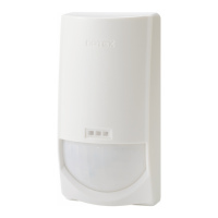
PHOTOELECTRIC DETECTOR
PHOTOELECTRIC DETECTOR
CONTENTS
1 INTRODUCTION
1-1 BEFORE YOUR OPERATION ............................... 2
1-2 PRECAUTIONS...................................................... 3
2 PARTS IDENTIFICATION............................................ 3
3 INSTALLATION
3-1 NOTE...................................................................... 4
3-2 INSTALLATION METHOD .................................... 4
4 WIRE CONNECTION................................................... 6
5 ALIGNMENT
5-1 OPTICAL ALIGNMENT .......................................... 7
5-2 BEAM INTERRUPTION TIME................................ 8
5-3 SELECTABLE BEAM FREQUENCIES
< AX-100/200TF ONLY >....................................... 8
6 WALK TEST................................................................. 9
7 SPECIAL FUNCTION < AX-100/200TF ONLY >
7-1 ENVIRONMENTAL DISQUALIFICATION.............. 9
7-2 ALARM MEMORY.................................................. 9
8 OPTIONAL ACCESSORIES
8-1 HEATING UNIT : HU-3......................................... 10
8-2 BACK COVER : BC-3........................................... 11
8-3 POLE SIDE COVER : PSC-3 ............................... 11
9 TROUBLESHOOTING............................................... 12
10
SPECIFICATIONS
10-1 SPECIFICATIONS.............................................. 13
10-2 DIMENSIONS & OPTION................................... 14
INSTALLATION INSTRUCTIONS
FEATURES
No.59-2419-1 1701-31
No.59-1282-7 0904-30
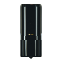
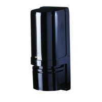
AX-70TN, AX-130TN, AX-200TN
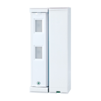
AX-100TF, AX-200TF
< AX-70/130/200TN, AX-100/200TF >
•High-performance waterproof structure
•Horizontal alignment dial for user-friendliness
•Adjustable beam interruption period
•Tamper function
•
Optional Accessories : Heating unit (HU-3), Back cover (BC-3),
Pole side cover (PSC-3)
•UL Listed
< AX-100/200TF ONLY >
•4 selectable beam frequencies
•LED indicator for fine beam alignment level
•D.Q. circuit (Environmental disqualification)
•Alarm memory
AX-200TN 60 m / 200 ft.
30 m / 100 ft.
4 selectable beam
frequencies
60 m / 200 ft.
AX-100TF
AX-200TF
Model Detection range Feature
20 m / 70 ft.
40 m / 130 ft.
Standard model with
detection range
60 m / 200 ft.
AX-70TN
AX-130TN
UL
AX-70TN, AX-130TN, AX-200TN
AX-100TF, AX-200TF