INSTALLATION INSTRUCTIONS
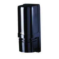
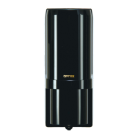
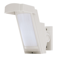
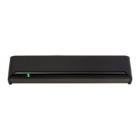
PHOTOELECTRIC DETECTOR
AX-330PLUS
• LED indicator for beam alignment level:
Accurate and reliable alignment can be easily achieved by using LED indicator located on the receiver.
The alarm indicating lamp is located in the front end of the inner housing and in viewfinder.
• Aligned fine angle adjustment:
By turning the dial, you can achieve vertical and horizontal optical adjustments.
• Form C relay:
Suitable for various applications.
• Anti-frost structure:
The front cover prevents fog and condensation from blocking the beams.
• Beam interruption time adjustment:
This feature allows you to select suitable beam interruption time for any environment.
• Alignment-level monitor jack
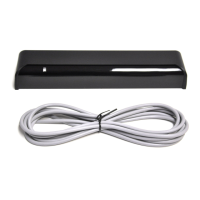
• Optional accessories ( not included):
Heating unit (HU-2), Back cover (BC-2)
PHOTOELECTRIC DETECTOR
AX-330PLUS
FEATURES
Warning
Caution
• Read this instruction manual carefully prior to installation.
• After reading, store this manual carefully in an easily accessible place for reference.
• This manual uses the following warning indications for correct use of the product, harm to you or other people and damage to your assets, which
are described below. Be sure to understand the description before reading the rest of this manual.
INTRODUCTION
1
1-1
BEFORE YOUR OPERATION
Failure to follow the instructions provided with this indication and improper handling may cause
death or serious injury.
Failure to follow the instructions provided with this indication and improper handling may cause
injury and/or property damage.
This symbol indicates prohibition. The specific prohibited action is provided in and/or around the figure.
This symbol requires an action or gives an instruction.
Warning
Caution
Do not use the product for purposes other than the detection of moving objects such as
people and vehicles. Do not use the product to activate a shutter, etc., which may
cause an accident.
Do not touch the unit base or power terminals of the product with a wet hand (do not
touch when the product is wet with rain, etc.). It may cause electric shock.
Never attempt to disassemble or repair the product. It may cause fire or damage to the
devices.
Do not exceed the voltage or current rating specified for any of the terminals during
installation, doing so may cause fire or damage to the devices.
Do not pour water over the product with a bucket, hose, etc. The water may enter,
which may cause damage to the devices.
Clean and check the product periodically for safe use. If any problem is found, do not
attempt to use the product as it is and have the product repaired by a professional
engineer or electrician.
No.59-2709-0 1712-25
Detection range
AX-330PLUS
100 m / 330 ft.
Model
- 1 -