35 (1.38")
130 (5.12")
30 (1.18")
2-2
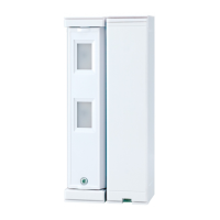
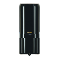
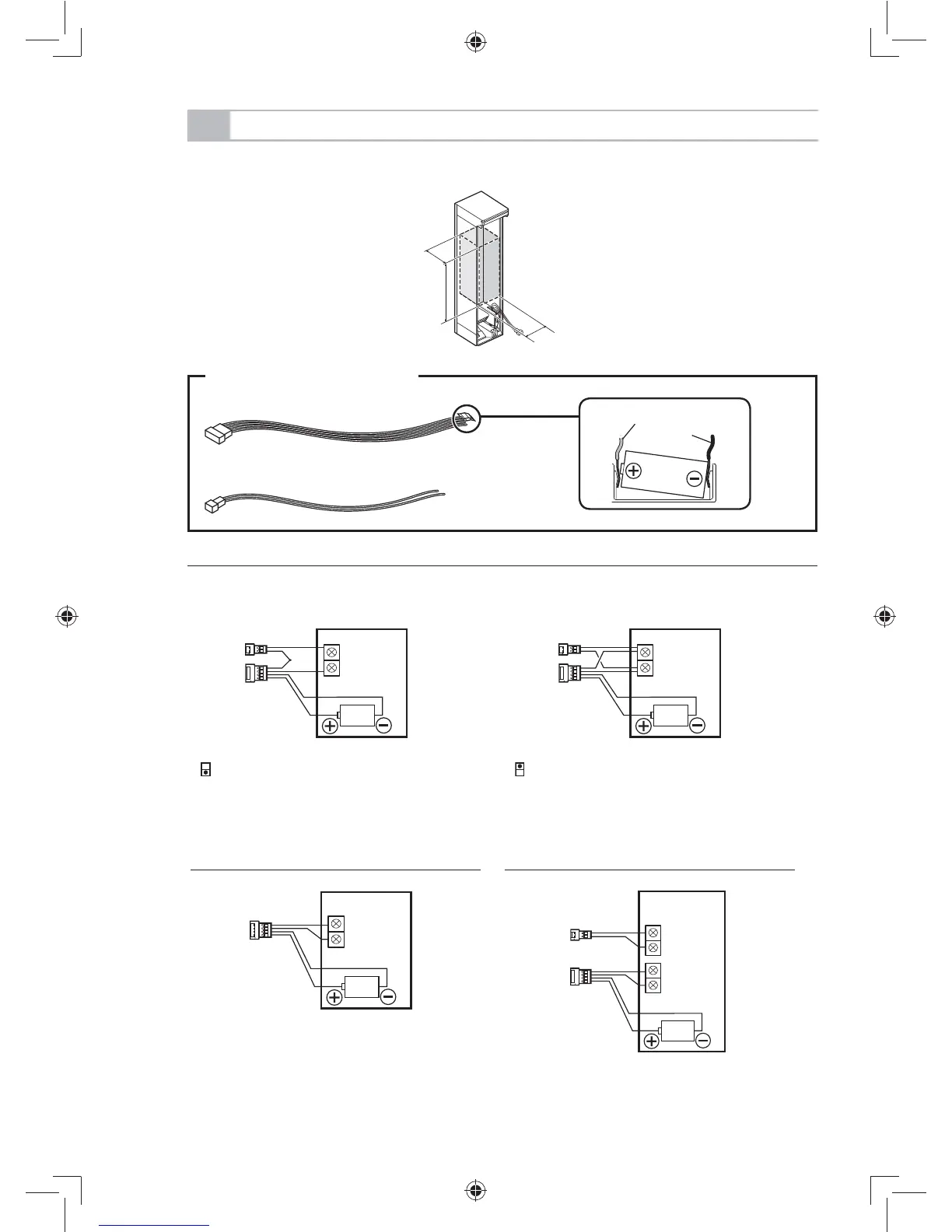
TRANSMITTER PREPARATION
The transmitter used should have the internal dimensions of H 130 × W 30 × D 35 mm.
(H 5.12" × W 1.18" × D 1.38")
- When monitoring ALARM and TROUBLE using the transmitter with 1 external input
External input is N.C. External input is N.O.
3
... DIP switch 3: OFF (N.C.)
3
... DIP switch 3: ON (N.O.)
-To monitor only the ALARM using a
transmitter with 1 external input
-To monitor the ALARM and TROUBLE
using a transmitter with 2 external inputs
Connectors to be used
Connector for POWER and ALARM
Connector for TROUBLE
Red
Black
How to position a battery
Connector for POWER
and ALARM
Connector for
TROUBLE
Connector for
POWER and ALARM
N.C. N.O.
Unit: mm (inch)
- 5 -
 Loading...