EN-1
CONTENTS
1 INTRODUCTION
1-1 PREPARATION........................................................................................... 1
1-2 PRECAUTIONS .......................................................................................... 1
1-3 PARTS IDENTIFICATION........................................................................... 2
1-4 DETECTION AREA..................................................................................... 2
1-5 INSTALLATION WORK FLOWCHART....................................................... 2
2 MOUNTING TYPE AND ASSEMBLY OPTIONS
2-1 MOUNTING TYPE ...................................................................................... 3
2-2 DISASSEMBLY ........................................................................................... 4
2-3 ASSEMBLY OPTIONS................................................................................ 4
3 BEFORE INSTALLATION
3-1 REMOVING THE FRONT COVER ............................................................. 6
3-2 MOUNTING THE FRONT COVER ............................................................. 6
3-3 REMOVING THE LASER WINDOW ........................................................... 6
3-4 MOUNTING THE LASER WINDOW ........................................................... 6
3-5 WIRING CABLE ENTRY ............................................................................. 6
3-6 INSTALLING NETWORK CABLE ............................................................... 7
4 INSTALLATION AND ANGLE ADJUSTMENT
4-1 WALL OR CEILING MOUNTED.................................................................. 7
4-2 ANGLE ADJUSTMENT ............................................................................... 7
4-3 LASER AREA CONFIRMATION ................................................................. 7
5 PARTS LAYOUT INSIDE AND THEIR FUNCTIONS
5-1 WIRING ....................................................................................................... 8
5-2 PROGRAMMABLE SIGNAL OUTPUT........................................................ 8
5-3 PROGRAMMABLE SIGNAL INPUT (RLS-2020S only) .............................. 8
5-4 ETHERNET PORT (PoE)............................................................................ 8
5-5 MAINTENANCE SECTION ......................................................................... 8
5-6 MAINTENANCE PORT ............................................................................... 8
5-7 POWERING ON .......................................................................................... 8
5-8 INITIALIZATION TO FACTORY DEFAULT ................................................ 8
5-9 LED INDICATOR......................................................................................... 8
6 SETTING
6-1 OVERVIEW ................................................................................................. 9
6-2 DETECTION CONFIGURATION ................................................................ 9
6-4 NETWORK OPTIONS............................................................................... 10
6-5 AUTHENTICATION..................................................................................
. 10
6-6 MAINTENANCE ........................................................................................ 11
6-7 REDWALL EVENT CODE......................................................................... 11
7 DIMENSIONS
7-1 DIMENSIONS............................................................................................ 11
8 SPECIFICATIONS
8-1 SPECIFICATIONS .................................................................................... 11
8-2 OPTIONS .................................................................................................. 12
9 APPENDIX
9-1 REPAINTING ............................................................................................ 12
FEATURES
1
INTRODUCTION
1-1
PREPARATION
• Read this instructions carefully prior to installation.
• This instructions uses the following warning indications to provide information
regarding correct usage of the product to prevent harm and damages to assets.
These warning indications are described below.
Ensure these precautions before reading the rest of this instructions.
Install the product so that the detection
area is not influenced by interference
from tall grass or tree branches waving
in the wind.
Do not install or leave the product in a
location exposed to heat, vibrations or
impacts.
Do not use the product in an
environment where solvent fumes or
corrosive gases are present.
NO. 59-2408-6
INSTALLATION INSTRUCTIONS
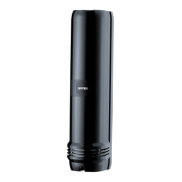
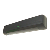
Indoor/Outdoor model
Indoor only
RLS-2020S
Laser Scan Detector
Laser Scan Detector
RLS-2020S
RLS-2020
RLS-2020
This symbol indicates prohibition.
The specific prohibited action is provided in and/or around the figure.
This symbol requires an action or gives an instruction.
This product is not a safety component as per the machinery directive.
Do not use it for the purpose of machine safety.
Do not touch the unit base or power terminals of the product with a wet
hand (do not touch when the product is wet with rain, etc.). It may cause
electric shock.
Never attempt to disassemble or repair the product. It may cause fire or
damage to the devices.
Do not exceed the voltage or current rating specified for any of the
terminals, doing so may cause fire or damage to the devices.
Ensure the power is turned off before wiring.
Confirm the type of each terminal to ensure wiring is carried out correctly.
Whenever a commercial switching regulator is used, be sure to connect
PE (Protective Earth Terminal).
Clean and check the product periodically for safe use.
If any problem is found, do not attempt to use the product as it is.
When disposing of this product, be sure to follow the waste-disposal
regulations of the country or region where it is used.
Hold the main unit securely when you install or service it. Exercise care
not to bump the product against nearby objects or drop it inadvertently.
This product is not capable of detecting objects in the dead zone of the
laser scan.
Do not use this product for an application where it is not capable of
covering the detection area required by the task.
Please note that the product can malfunction, including producing an
irregular output and committing a detection error, if it is exposed to
unfavorable environmental conditions such as strong ambient light,
electronic noises or mechanical vibrations.
Use of controls or adjustments or performance of procedures other than
those specified herein may result in hazardous radiation exposure.
This product is intended to detect an intruder(s) and is not designed to
prevent theft, disasters or accidents. The manufacturer shall not be held
liable for any damage to user’s property resulting from theft, disasters or
accidents.
Do not use this product in environments where there may be oil mist particles
which may contaminate the window of the detector; thus causing detection errors
and possible corrosion which may lead to product failure.
There should not be any obstructs (e.g. lighting equipment, fire detectors,
cameras, poster, etc.) in the laser area.
After installation, any obstructs should not be carried/moved into the detection area.
• 20 x 20 m (65 x 65 ft.), 95 degrees detection area
• Vertical and Horizontal detection area
• Multi-angle Adjustment Shell Structure (M.A.S.S.)
• Automatic area setting function
• Advanced area setting
• 4 adjustable detection areas on IP connection
• Total 3 outputs can be assigned for analog connection
• Anti-masking, Anti-rotation, Soiling, Device trouble, Tamper output (selectable)
• Paintable housing
• Supporting multiple network protocols
RLS-2020S
• Indoor and Outdoor use
• Indoor high resolution mode
• Indoor throw-in mode
• Area selection
• Environmental disqualification circuit (DQ)
1-2
PRECAUTIONS
mini
The check mark indicates recommendation.
Caution
Warning
EN
(UL) 59-2408-4 1703-01
Failure to follow the instructions provided with this indication and
improper handling may cause death or serious injury.
Failure to follow the instructions provided with this indication and
improper handling may cause injury and/or property damage.
Install the product only on a solid
surface.
Do not install the product on an
uneven surface.
Avoid mounting near vents or devices
which cause high levels of smoke or
condensation.
Warning
Caution
SECURITY
U
L
LISTED
R
6-3 NETWORK CONFIGURATION................................................................. 10