BIOLINE Manual for installation and use
OPTIKON 2000
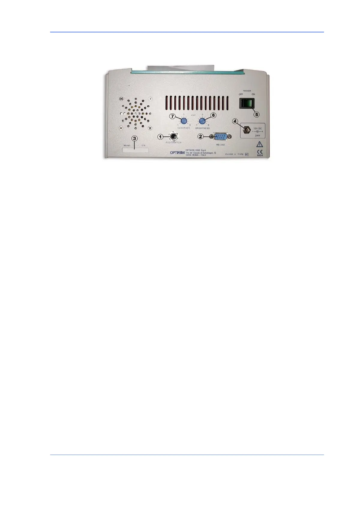
REAR PANEL (FIG.2)
1) FOOTSWITCH SOCKET
Input for the footswitch connector (optional). The footswitch closes down and
reactivates the biometric measurement on the acquisition page (in a similar way to
the A-SCAN key).
2) RS232 CONNECTOR
Socket for possible connection to a computer (not supported by the current version of
the programme).
3) PLATE
Shows the data on the instrument plate and the serial number.
4) SUPPLY INPUT
Input socket (low voltage) for connection to the feeder model 142001/142002 or to
another source with equivalent characteristics.
5) MAIN SWITCH
Activates and deactivates the instrument supply (display of the symbol “O” indicates
the off position).
6) BRIGHTNESS CONTROL
This small potentiometer allows the back lighting of the screen to be adjusted from 1
to 9. Adjust to achieve good screen visibility.
7) LCD CONTRAST
This small potentiometer allows the screen contrast to be adjusted in an optimum
way, depending on the visual angle of the screen.
Code 141002EN 7-3 26.10.05 Rev.0