Do you have a question about the Optimum DRO 5 and is the answer not in the manual?
Guidelines for safe installation and operation, including warnings and warranty claims.
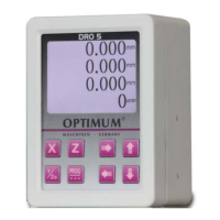
Defines the purpose of the DRO5 as a high-precision measuring system using external sensors.
Explains safety notes, signal signs, signal words, and danger classes for user safety.
Identifies qualified and unqualified personnel for installation, commissioning, and maintenance.
Lists all components included in the package, such as the digital display, magnetic plates, and cables.
Details optional accessories such as magnetic tapes with different lengths and resolutions.
Covers the physical mounting of the device, including precautions and assembly steps.
Provides warnings and instructions for the electrical connection of the device to prevent damage.
Details the pin assignment and specifications for the 6-pin TTL differential signal socket.
Describes the function of each key on the control panel, including selection and navigation keys.
Explains how to perform basic operations like clearing axis values and modifying basic values.
Guides access to main menu options for LCD display settings, unit selection, and language.
Adjusts display parameters like contrast and backlight, and selects RGB display types.
Configures parameters for individual X, Y, Z axes and the speed axis.
Sets sensor type (e.g., MS200) and resolution (e.g., 50 microns) for the X-axis.
Sets the counting direction for the axes, typically using '+/-' selection.
Configures the display mode of the DRO, such as 'On / Off' for specific readouts.
Allows compensation for linear errors to improve measurement accuracy.
Configures speed axis parameters, including teeth amount per revolution and display mode.
Details installation requirements to protect against environmental influences like water, dust, and vibrations.
Provides instructions on preparing the surface and applying the magnetic strip for accurate measurement.
Step-by-step guide for cleaning surfaces, applying the magnetic strip, and fixing the cover strip.
Illustrates various mounting methods for the magnetic strip to ensure protection and proper alignment.
Guides on fixing the magnetic sensor, cable management, and alignment with the magnetic tape.
Explains how to select the location and wiring to minimize capacitive or inductive interference.
Recommends positioning sensors away from interference sources and using protective measures.
Recommends cleaning the magnetic strip surface periodically to prevent dirt buildup.
Lists common installation and operation errors, such as incorrect mounting or sensor connection.
| Display Type | LCD |
|---|---|
| Resolution | 800 x 480 pixels |
| Backlight | LED |
| Screen Size | 5 inches |
| Interface | VGA |
| Operating Temperature | 0°C to 50°C |
| Storage Temperature | -20°C to 60°C |
| Weight | 220g |