OPTIMUM
MASCHINEN - GERMANY
Version 1.0.4 dated 2015-11-19Page 18 Original operating instructions
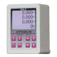
DRO 5GB
1.5 Basic safety information
DANGER OF EXPLOSION!
Do not use the electronic display in explosive zones.
2 Identification
The type label shows the model name with model number and serial number.
2.1 Scope of delivery
Digital Position Indicator DRO5
Magnetic plate 60 x 46mm with countersunk head screws for fixing the housing on side or bottom.
4 pcs. Plastic closing caps for threaded holes in the housing.
Speed sensor, cable length 5 meters
Connection cable power supply, cable length 6 meters
3 pcs. Magnetic sensors MS200 = MR000, without magnetic tape.
2.2 Optionally available
Magnetic tape item no. 3383978 - Length in a piece - 1100 mm ,
Resolution 0.05 mm (50ɥm)
Magnetic tape item no. 3383979 - Length in a piece - 2000 mm ,
Resolution 0.05 mm (50ɥm)
Magnetic tape item no. 3383980 - Bulk stock,
Resolution 0.05 mm (50ɥm)
3 Installation
3.1 Mechanical installation
CAUTION!
Failure of electronic display
When mounting pay attention to the IP type of protection.
Make absolutely sure to close not used fixing holes in the housing with enclosed plastic caps.
Avoid impact on the device.
Do not modify the device in any way.
Assembly
Fasten the device via the threaded holes (2x M5, 7 deep) onto the bottom side or onto a flat working sur-
facewith the magnet plate.
The mounting surface should be made for better grip with a suitable cleaning agent fat or oil-free.
Device dimension: height 134mm, width 98.5mm, depth 65.5mm
3.2 Electrical installation
WARNING!
Destruction of parts of equipment and loss of regulation control
Check all line connections and plug connections before switching on supply voltage.