OPTIMUM
MASCHINEN - GERMANY
Version 1.0.1 dated 2017-08-10 Page 3Translation of the original instructions
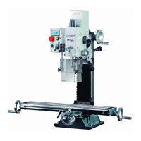
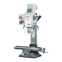
MH50G│MH50V GB
3.3.3 Assembly.....................................................................................................................................23
3.4 Dimensions, balance point .....................................................................................................................24
3.5 Mounting on the optionally available machine base............................................................................... 26
3.6 First commissioning................................................................................................................................ 27
3.7 Cleaning and lubrication......................................................................................................................... 28
3.8 Electrical connection .............................................................................................................................. 28
3.8.1 MH50G and MH50V.................................................................................................................... 28
3.8.2 MH50V ........................................................................................................................................ 29
3.8.3 Regulated drives in connection with residual current devices..................................................... 30
3.8.4 Protection from Dangerous Shock Currents, use of ELCBs ....................................................... 30
3.8.5 Current in the protective earth conductor - Leakage current....................................................... 30
3.8.6 When the ELCB triggers ............................................................................................................. 31
4Operation
4.1 Control and indicating elements ............................................................................................................. 32
4.1.1 Control panel...............................................................................................................................33
4.2 Safety ..................................................................................................................................................... 34
4.3 Switching the milling machine on ........................................................................................................... 34
4.4 Switching the milling machine off ........................................................................................................... 34
4.5 Resetting an emergency stop situation ..................................................................................................34
4.6 Power failure, Restoring readiness for operation ................................................................................... 34
4.7 Speed setting ......................................................................................................................................... 34
4.7.1 Selecting the speed.....................................................................................................................34
4.7.2 Gear stage ..................................................................................................................................35
4.8 Direction of spindle rotation.................................................................................................................... 35
4.9 Feed ....................................................................................................................................................... 35
4.10 Spindle quill feed .................................................................................................................................... 36
4.10.1 Setting the drilling or tapping depth............................................................................................. 36
4.11 Tapping .................................................................................................................................................. 36
4.12 Milling head rapid traverse ..................................................................................................................... 37
4.13 Inserting or Removing Tool .................................................................................................................... 37
4.13.1 Inserting ...................................................................................................................................... 37
4.13.2 Removing....................................................................................................................................38
4.14 Clamping the workpieces .......................................................................................................................38
4.14.1 Calculation of the Cutting Forces or Necessary Holding Force when Milling..............................39
4.15 Swivelling the milling head ..................................................................................................................... 39
5 Maintenance
5.1 Safety ..................................................................................................................................................... 40
5.1.1 Preparation.................................................................................................................................. 40
5.1.2 Restarting.................................................................................................................................... 40
5.2 Inspection and maintenance .................................................................................................................. 40
5.3 Repair..................................................................................................................................................... 43
5.3.1 Customer service technician....................................................................................................... 43
6 Ersatzteile - Spare parts
6.1 Fräskopf - Milling head 1 - 4................................................................................................................... 44
6.2 Fräskopf - Milling head 2 - 4..................................................................................................................45
6.3 Fräskopf - Milling head 3 - 4................................................................................................................... 46
6.4 Fräskopf - Milling head 4 - 4................................................................................................................... 47
6.5 Säule - Column 1 - 2 .............................................................................................................................. 48
6.6 Säule - Column 2 - 2 .............................................................................................................................. 49
6.7 Kreuztisch - Cross table 1 - 2 .................................................................................................................50
6.8 Kreuztisch - Cross table 2 - 2 .................................................................................................................51
6.9 Schutzeinrichtung - Protection device ....................................................................................................52
6.10 Schaltschrank - Switch cabinet .............................................................................................................. 52
6.11 Schaltplan - Wiring diagram - MH50G.................................................................................................... 57
 Loading...