Do you have a question about the Optimum OPTImill BF 20V and is the answer not in the manual?
Explains symbols and their meanings for safety warnings.
Details the identification plates on the machine for model and specifications.
Classifies safety warnings and their consequences.
Categorizes safety warnings by danger level and consequence.
Illustrates and explains additional safety pictograms used in the manual.
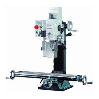
Defines the proper and intended application of the drilling-milling machine.
Outlines forbidden uses and how to avoid incorrect operation.
Lists potential hazards associated with the machine's operation.
Specifies the required qualifications for operating and maintaining the machine.
Describes the standard position for operating the drilling-milling machine.
Outlines essential precautions to ensure safety while operating the machine.
Description and function of the emergency stop button.
Information on the protective cover for the drilling/milling head.
Details on the protective equipment for the milling spindle.
Procedures for regularly checking the machine's safety features.
Required personal protective equipment (PPE) for safe operation.
General safety recommendations for operating the machine.
Procedures for safely switching off and securing the machine.
Guidelines for safely using lifting equipment with the machine.
Explains the various warning and information signs on the machine.
Details the machine's electrical power requirements and connection.
Specifies the drilling and milling capabilities of the machine.
Information regarding the spindle taper and sleeve.
Technical specifications for the drilling and milling head.
Dimensions and specifications of the machine's cross table.
Overall physical dimensions of the machine.
Dimensions of the machine's operational working area.
Information on the spindle speed ranges and gear stages.
Recommended operating temperatures, humidity, and materials.
Information regarding noise emissions from the machine.
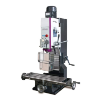
Detailed installation layout and dimensions for the BF20V model.
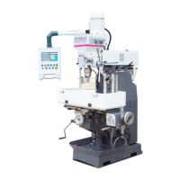
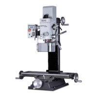
Installation layout and dimensions for BF20L and BF20LD models.
Installation guide for an optional substructure.
Lists the items included in the machine's delivery package.
Guidelines and warnings for safely transporting the machine.
Detailed instructions for installing and assembling the machine.
Steps and precautions for the initial startup of the machine.
List and details of optional accessories available for the machine.
Essential safety requirements before operating the machine.
Identification and function of the machine's control panel elements.
Step-by-step guide to starting up the machine.
Procedures for safely shutting down the machine.
Instructions for correctly inserting tools into the spindle.
Instructions on how to securely clamp workpieces.
How to select different gear stages for speed control.
Guidance on selecting the appropriate spindle speed for milling.
Tables of recommended cutting speeds for various materials and tools.
Recommended speeds for drilling with HSS tools.
How to use the fine feed mechanism for spindle sleeve adjustment.
Operation and features of the digital display for spindle sleeve movement.
Troubleshooting common issues with the digital display.
Using the spindle sleeve lever for feed adjustment.
How to adjust the angle of the drill-mill head.
Instructions for installing an optional high-speed motor adapter.
Steps for mounting the machine column onto a lathe.
Explanation of the digital readout system's keyboard functions.
General procedures for operating the DRO 5 system.
Navigating the menu system of the DRO 5.
Overview of the main menu options for the DRO 5.
Customizing display settings like contrast and backlight.
Configuring parameters for the machine's axes and speed.
Setting specific parameters for the X-axis measurement.
Setting parameters for the speed axis measurement.
Information on connecting sensors and power to the DRO 5.
Safety precautions to be followed during maintenance activities.
Schedule and procedures for routine inspection and maintenance.
Exploded view and part list for the cross table assembly.
Exploded view of the machine column (part 1).
Spare parts specific to the BF20LD model.
Exploded view of the machine column (part 2).
Exploded view of the milling head (part 1).
Exploded view of the milling head (part 2).
Spare parts for the control panel and safety guards.
Spare parts for the optional machine substructure.
Electrical wiring diagram for BF20V and BF20L models.
List of machine labels and their identification numbers.
Comprehensive list of all spare parts with numbers and specifications.
Troubleshooting guide for common machine problems and their solutions.
Legal copyright information regarding the manual's content.
Definitions of technical terms used in the manual.
Records of changes made to manual versions.
Information on warranty terms and conditions.
Guidelines for environmentally friendly disposal and reuse.
Instructions for proper storage of the machine and its components.
Information on post-shipment follow-up services and feedback.
| Motor Power | 850 W |
|---|---|
| Voltage | 230 V |
| Table Size | 700 x 180 mm |
| Y-Axis Travel | 175 mm |
| Z-Axis Travel | 280 mm |