Version 4.0.2 dated 2019-4-3 Page 69Translation of the original instructions
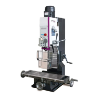
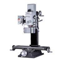
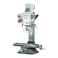
BF20V | BF20L | BF20LD GB
BF20V_BF20L_BF20LD_GB_8.fm
OPTIMUM
MASCHINEN - GERMANY
®
9 Appendix
9.1 Copyright
This document is copyright. All derived rights are also reserved, especially those of translation,
re-printing, use of figures, broadcast, reproduction by photo-mechanical or similar means and
recording in data processing systems, neither partial nor total.
Subject to technical changes without notice.
9.2 Terminology/Glossary
9.3 Change information manual
Term Explanation
Cross table Bearing surface, clamping surface for the workpiece with X- and Y-
axis travel
Taper mandrel Cone of the drill or of the drill chuck
Workpiece Piece to be milled, drilled or machined.
Draw-in rod Threaded rod to fix the taper mandrel in the spindle sleeve.
Drill chuck Device for holding the bit
Collet chuck Holder for end mill
Drilling and milling head Upper part of the drilling-milling machine
Spindle sleeve Hollow shaft in which the milling spindle turns.
Milling spindle Shaft activated by the motor
Drilling table Supporting surface, clamping surface
Taper mandrel Cone of the drill or of the drill chuck
Spindle sleeve lever Manual operation for the drill feed
Quick action - drill chuck Drill chuck can be fixed by hand.
Workpiece Piece to be drilled or machined.
Tool Milling cutter, drill bit, etc.
Chapter short information new version number
1.3.1 Avoiding misuses 3.1.7
EC declaration changed standard 3.1.7
5.4 Setup Instructions motor control board 3.1.7
4.10 New digital display for spindle sleeve travel 3.1.8
DRO5 Digital display DRO5 integrated for BF20LD 4.0
4.2.1 + CE Designations 4.0.1
6.2 + 7 Maintenance, replacement of control card Q1.7 4.0.2