Version 4.0.2 dated 2019-4-3 Page 23Translation of the original instructions
BF20V | BF20L | BF20LD GB
BF20V_BF20L_BF20LD_GB_3.fm
OPTIMUM
MASCHINEN - GERMANY
®
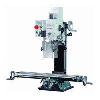
3.3 Installation and assembly
3.3.1 Requirements regarding the installation site
Organize the working area around the drilling-milling machine according to the local safety reg-
ulations.
INFORMATION
In order to attain good functionality and a high processing accuracy as well as a long durability
of the machine the installation site should fulfil certain criteria.
Please observe the following points:
The device must only be installed and operated in a dry and well-ventilated place.
Avoid places nearby machines generating chips or dust.
The installation site must be free from vibrations also at a distance of presses, planing
machines, etc.
The substructure must be suitable for the drilling-milling machine. Also make sure that the
floor has sufficient load bearing capacity and is level.
The substructure must be prepared in a way that possibly used coolant cannot penetrate
into the floor.
Any parts sticking out such as stops, handles, etc. have to be secured by measures taken
by the customer if necessary in order to avoid endangerment of persons.
Provide sufficient space for the staff preparing and operating the machine and transporting
the material.
Also consider that the machine is accessible for setting and maintenance works.
Provide for sufficient illumination (Minimum value: 500 lux, measured at the tool tip). At little
intensity of illumination an additional illumination has to be ensured e.g. by means of a sepa-
rate workplace lamp.
INFORMATION
The mains plug of the drilling-milling machine must be freely accessible.
3.3.2 Load suspension point
WARNING!
Danger of crushing and tilting. Proceed carefully when lifting, installing and assembling the
machine.
Fix the load lifting gear around the drilling-milling head. Use a lifting sling for this purpose.
lifting sling.
Firmly clamp all clamping levers on the drilling-milling machine before lifting the drilling-mill-
ing machine.
Make sure that the load attachment does not cause damage to components or paint.
3.3.3 Assembly
Check if the underground of the drilling-milling machine is level using a spirit level.
Check if the underground is sufficiently stable and rigid. The total weight 103 -112 kg.
ATTENTION!
Insufficient rigidity of the foundation leads to the superposition of
the vibrations of the drilling-milling machine and of the underground (natural frequency
of components). Critical speeds and moves in the axis with displeasing vibrations are
rapidly achieved in case of insufficient rigidity of the whole system and will lead to bad
milling results.