Version 4.0.2 dated 2019-4-3 Page 37Translation of the original instructions
BF20V | BF20L | BF20LD GB
BF20V_BF20L_BF20LD_GB_4.fm
OPTIMUM
MASCHINEN - GERMANY
®
4.14 Assembly of the column on the lathe
The machine BF20V and BF20L covered by the standard DIN EN 13128 (milling machines,
including drilling machines). The one who changed the BF20V and BF20L is legally the manu-
facturer of a new machine due to the significant change in the machine and is therefore respon-
sible for compliance with the requirements of the Machinery Directive and the DIN EN 13128.
The mill head with column can be
mounted on the lathe bed of the TU2506
and TU2807. An adapter is required to fix
it. It is not possible to fix it on the lathe
saddle.
The adapter is dimensioned in a way that
the center of the lathe chuck can be
reached with the centre of the milling
spindle (line tailstock - lathe chuck).
"Optional accessory“ on page 25
Due to the manufacturing tolerances of
cast parts and the manufacturing toler-
ances of two different machines, it ishow-
ever not possible to exactly reach the
centre. The adapter might be too short or
too long.
If required, the adapter has to be milled
or provided with dummy sheets. When
using dummy sheets, the complete sur-
face needs to be filled.
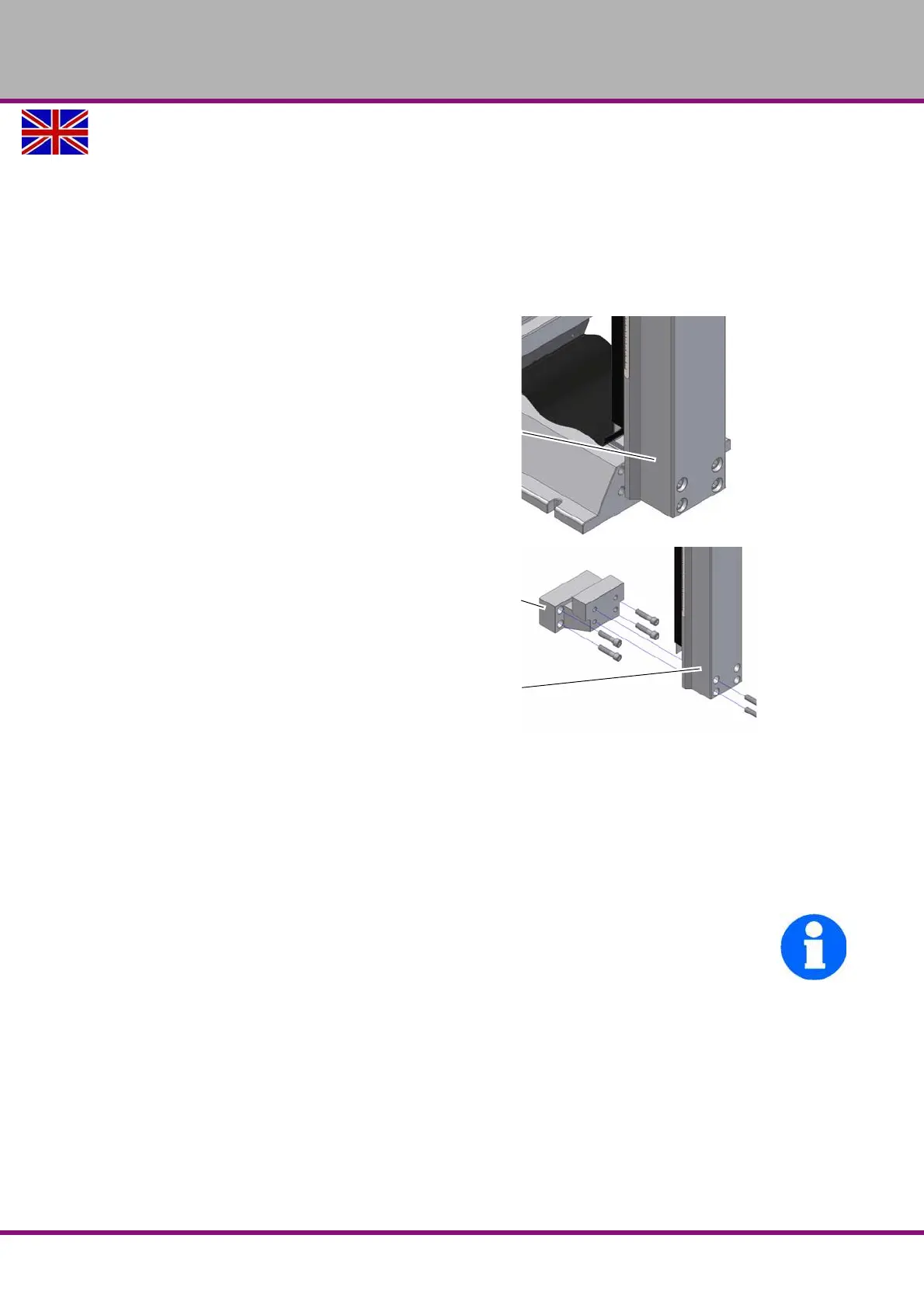
Img.4-14: Adapter
When aligning the column with the mill head mounted onto it, we recommend to disassemble
the mill head from the column in order to reduce the holding force of the column. Unscrew the
stud screw (screw) position 266. Disassemble the mill head from the column by completely
loosening the clamping screw and the guide screw and pull off the mill head.
Check the alignment (right angle horizontal and vertical) of the column regarding the reference
level at the lathe bed.
INFORMATION
In order to avoid the efforts of alignment when retrofitting it at a later time, we recommend you
to provide the column and the adapter as well as the adapter and the lathe bed with aligning
pins. If required, also pin the column to the cross table before disassembling the column. It is
most suitable to use hardened straight pins of 8mm or 10mm according to DIN 6325 and an
adjustment tolerance field m6 (e.g. DIN 6325-8 m6 x 30). These straight pins have a round cap
on one side which simplifies to stick the parts together. The holes have to be predrilled impera-
tively about 0,2mm smaller in the assembled status and have to be grinded with a reamer also
in the assembled status. Therefore, make sure to use a new spiral drill with a diameter of
7.8mm for the straight pins of 8mm.
Column
Adapter 3356572
Column