Version 4.0.2 dated 2019-4-3 Page 29Translation of the original instructions
BF20V | BF20L | BF20LD GB
BF20V_BF20L_BF20LD_GB_4.fm
OPTIMUM
MASCHINEN - GERMANY
®
4.5 Inserting a tool
4.5.1 Installation
WARNING!
When milling operations are performed the cone seat must always be fixed to the draw-
in rod. For milling operations it is not allowed to perform any cone connections with the
taper bore of the work spindle without using the drawing rod. The cone connection
should be released by the lateral pressure. Injuries may be caused by parts flying off.
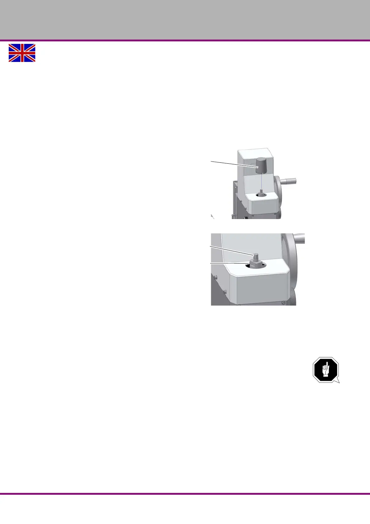
The milling head is equipped with a draw-in rod M10.
Remove the cap.
Clean the seat in the spindle / quill.
Clean the taper of your tool.
Insert the tool in the spindle / quill.
Img.4-4: Drilling and milling head
Screw the draw-in bar in the tool.
Tighten the tool with the draw-in rod
and hold the spindle on the counter
bearing by means of a wrench.
Img.4-5: Drilling and milling head
4.5.2 Disassembly
Hold the spindle counter bearing with a wrench and loosen the draw-in rod. Continue turn-
ing the draw -in rod, so that the tool is squeezed out from the conical collet.
ATTENTION!
When installing a cold morse taper into a heated-up machine those MT seats tend to
shrink on the morse taper contrary to the quick-releaser tapers.
4.5.3 Use of collet chucks
When using collet chucks for the reception of milling tools, a higher operation tolerance can be
achieved. The exchange of the collet chucks for a smaller or larger end mill cutter is performed
simply and rapidly and it is not necessary to disassemble the complete tool. The collet chuck is
pressed into the ring of the swivel nut and must rest there by itself. The milling cutter is clamped
by fastening the swivel nut on the tool. Make sure that the correct collet chuck is used for each
milling cutter diameter, so that the milling cutter may be fastened securely and firmly.
"Optional accessory“ on page 25
Draw-in rod
Steady/
counter bearing