IT-100 v1.2 4
VERY IMPORTANT!
The telephone connection must be made with an analog exchange extension or an analog outside line.
The dialling system must use DTMF tones.
Contents
1. GENERAL INFORMATION .......................................................................................................... 4
2. FRONT VIEW .......................................................................................................................... 4
3. REAR VIEW ............................................................................................................................ 5
4. BLOCK DIAGRAM .................................................................................................................... 6
5. CONFIGURATION .................................................................................................................... 7
6. OPERATION ............................................................................................................................ 9
7. TECHNICAL SPECIFICATIONS ................................................................................................. 10
8. DOCUMENT VERSION TRACKING ............................................................................................ 11
9. WALL MOUNTING KIT: Z-110 (not included) ............................................................................. 11
10. DIN RAIL MOUNTING KIT: Z-111 (not included) ...................................................................... 12
11. SINGLE MOUNTING KIT: Z-112 (not included) ........................................................................ 13
12. DOUBLE MOUNTING KIT: Z-113 (not included) ....................................................................... 13
13. GUARANTEE ....................................................................................................................... 14
1. GENERAL INFORMATION
The IT-100 is an independent (stand-alone) DTMF telephone interface. It provides access to the P.A.
system from the telephony installation.
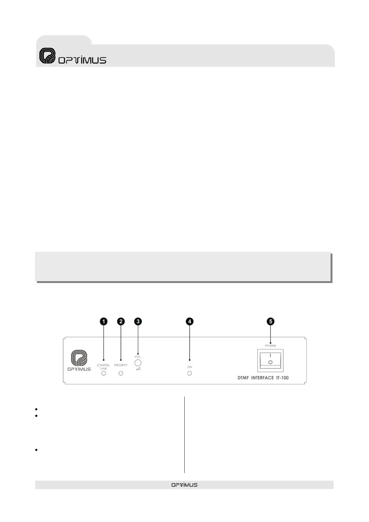
2. FRONT VIEW
(1) CONFIG. LINE INDICATOR: Yellow LED.
Slow blink: Module in standby mode (READY).
Fast blink: Starts to blink when the CONFIG.
button is pressed. This indicates that the
module is in configuration mode. Once the
module answers, the LED remains
permanently lit.
Permanently lit: This indicates that the
module is broadcasting a message or the
configuration parameters are being entered
from a telephone call.
(2) PRIORITY: Yellow LED indicating priority
(on standby turned off). It lights when a
telephone call is made.
(3) VOLUME: Front volume control. (If the rear
VOLUME BYPASS jumper is ON, this volume does
not work).
(4) ON LED: Blue LED indicating module is on.
(5) POWER SWITCH: ON/OFF switch