IT-100 v1.2 6
(7) DIPSWITCH: Configures the audio output level.
(8) CONFIG. BUTTON: This is used to configure the internal parameters of the telephone module.
(9) CONFIG. LED:
Slow blink: Module in standby mode (READY).
Fast blink: Starts to blink when the CONFIG. button is pressed. This indicates that the module is in
configuration mode. Once the module answers, the LED remains permanently lit.
Permanently lit: This indicates that the module is broadcasting a message or the configuration
parameters are being entered from a telephone call.
(10) PHONE LINE IN:
RJ-11 connector.
Analog telephone line
connection.
(11) INPUT LEVEL
ADJUST: Posterior
audio level adjustment
of the telephone
module.
(12) JUMPER: Ground
to chassis connection.
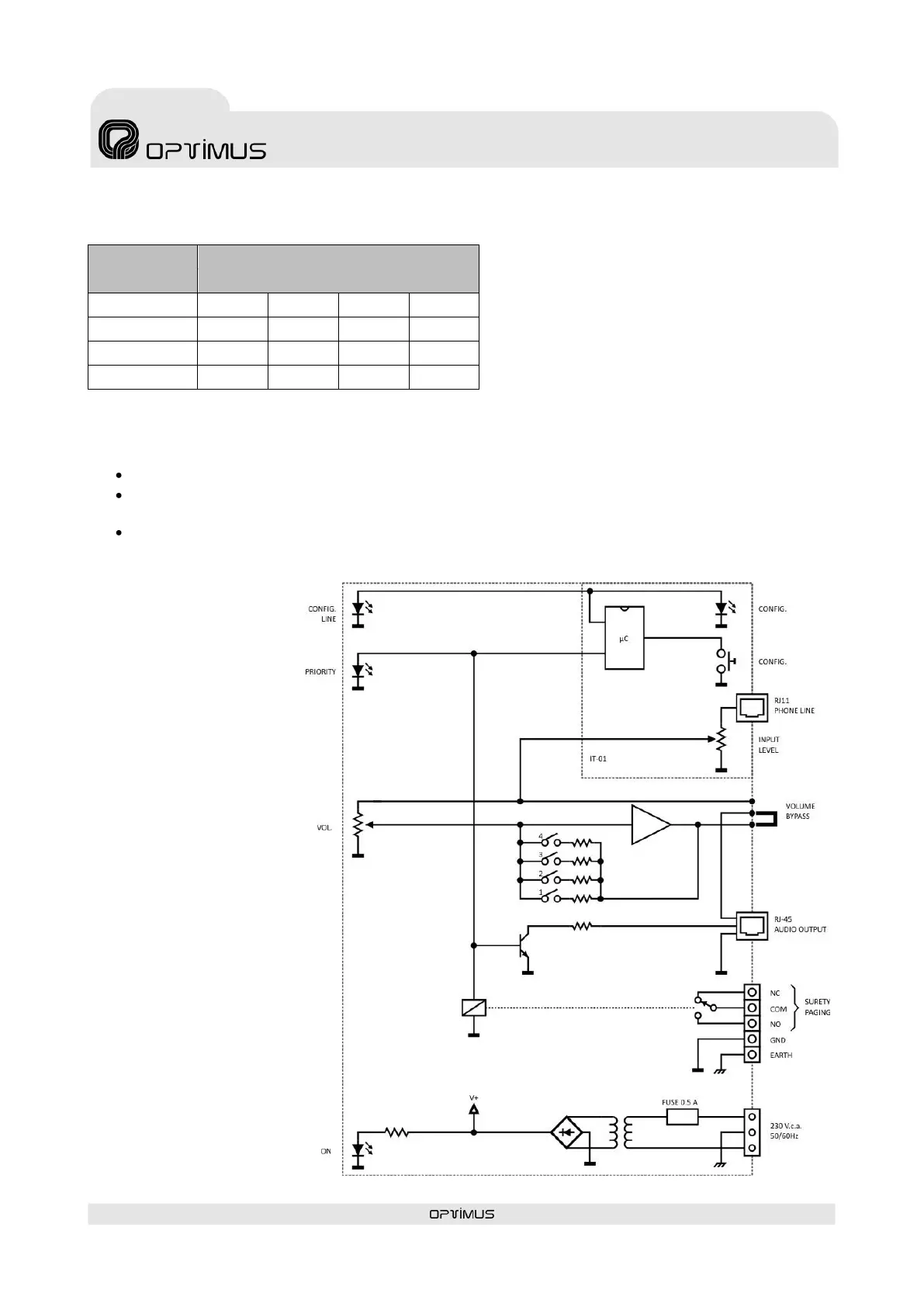
4. BLOCK
DIAGRAM
Factory setup configuration