M130 Version 1.0 Page 17 of 23
M130
8x8 Audio Matrix
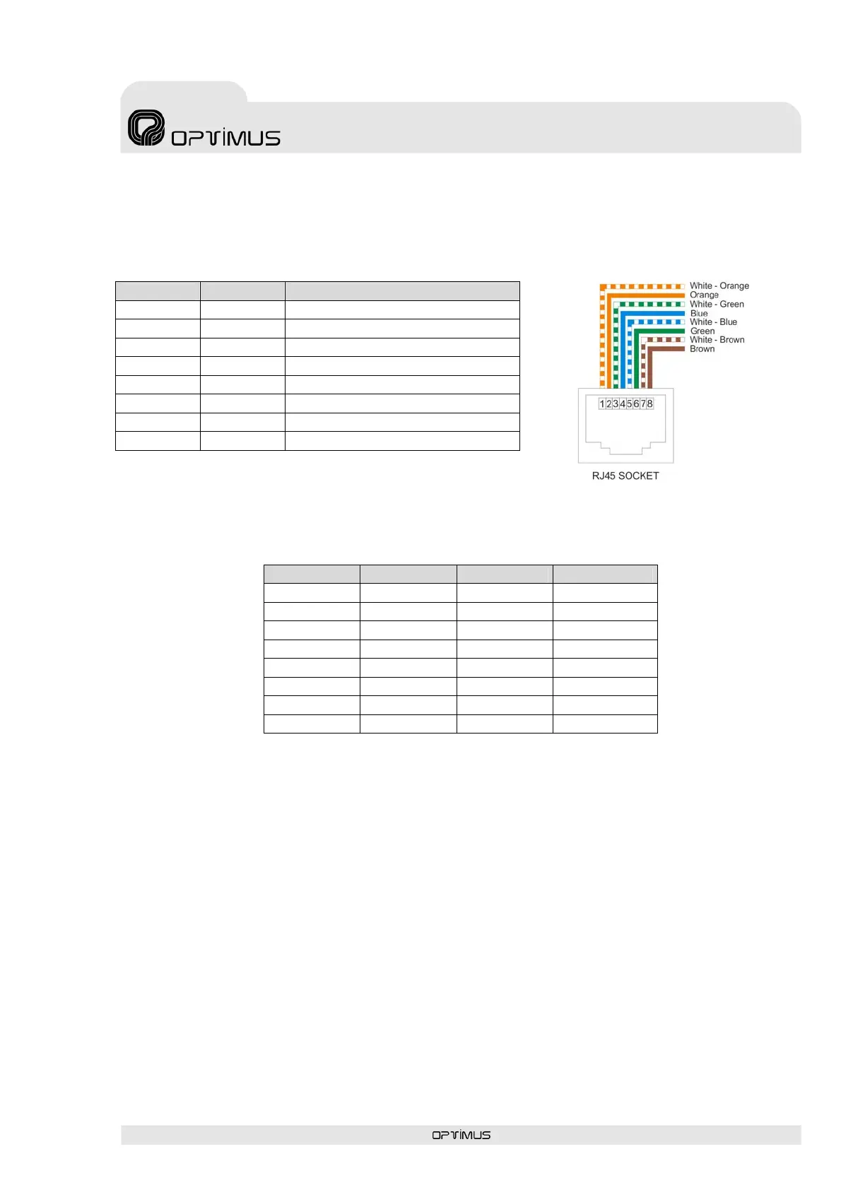
8. Connector to the M130 matrix.
The connector Pin description of the remote control M134P and M134T (RJ45 CAT5 UTP) is
as follows:
PIN Nº Name Description
1 Tx+ Positive transmission RS-422
2 Tx- Negative transmission RS-422
3 Rx- Negative reception RS-422
4 DC output +24 VDC power
5 GND Digital ground
6 Rx+ Positive reception RS-422
7 Audio + Balanced audio positive
8 Audio - Balanced audio negative
9. Follow the table below to configure the address of the remote controls:
DIP switch 1 DIP switch 2 DIP switch 3 Zones
OFF OFF OFF Zone 1
ON OFF OFF Zone 2
OFF ON OFF Zone 3
ON ON OFF Zone 4
OFF OFF ON Zone 5
ON OFF ON Zone 6
OFF ON ON Zone 7
ON ON ON Zone 8