Do you have a question about the Optimus UP-247 and is the answer not in the manual?
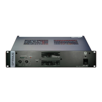
Displays power level; 0 dB indicates maximum power.
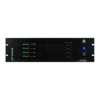
Controls program channel volume by turning clockwise; knobs are removable.
Controls priority channel volume by turning clockwise; knobs are removable.
Lights up when priority channel is selected via pin connection.
Indicates protection circuit activation due to overload, short circuit, or overheating.
Must be kept unobstructed at all times for proper airflow.
Lights up when amplifier is connected to mains or battery power.
Turns amplifier on/off when connected to 230V a.c. mains supply.
Connects amplifier to mains supply using a CEE 22 plug.
Located under power inlet; compartment also contains a spare fuse.
Allows connection to 24V d.c. battery for safety installations.
Ensures proper grounding in loudspeaker systems for signal integrity.
Activated when protection fails or amplifier power is off.
Rear panel ground contact point for electrical grounding.
Rear panel chassis contact point for grounding.
Outputs for loudspeakers without a line transformer, matching amplifier impedance.
Outputs for 50V, 70V, 100V lines, requiring loudspeakers with line transformers.
Disables RJ45 PRIORITY OUTPUT priority contact when OFF.
Disables RJ45 PRIORITY INPUT priority contact when OFF.
Links audio signals between PRIORITY OUTPUT and PROGRAM INPUT.
Allows separation of cable shield from the unit's internal mass.
Details claiming rights, requiring original invoice and warranty certificate.
Lists conditions voiding or limiting guarantee, and exclusions.
States guarantee is solely for the original purchaser and is not transferable.
Defines the limits of OPTIMUS S.A.'s responsibility for damages.
Clarifies guarantee relation to national laws and consumer rights.