Do you have a question about the Optimus UP120M4 and is the answer not in the manual?
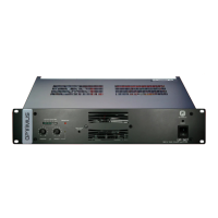
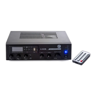
Details the UP-120M4 amplifier's construction and suitability for public address systems.
Indicates power output level with a 0 dB LED for maximum power.
Signals when a Priority channel is activated via RJ45 connector pins.
Indicates amplifier protection activation due to overload or short-circuit.
Important note to not obstruct the ventilation input under any circumstances.
Controls to adjust the volume of the Priority channels using a screwdriver.
Controls to adjust the volume of the Program channels using a screwdriver.
LED that lights up when the amplifier is operating on Battery or Mains.
Switch for powering the amplifier on/off from 230 Vac mains; inactive on battery.
Relays that activate with priority contacts of PRIORITY channels.
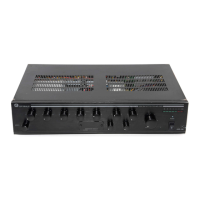
Outputs for low impedance (8 Ohms) and high impedance (70-100 V) speakers.
Connection method for mains power using the CEE22 supply connector.
Located in the power supply base, includes a spare fuse.
Input for connecting a 24 V.d.c. battery for security installations.
Guidance on proper grounding for PA installations to prevent issues.
Specifies the fan operation and cooling system of the amplifier.
Procedure for adjusting oscillation signal level for optional circuits.
Details terminal block for activating amplifier priority and installation wiring.
Description of RJ45 connectors for program and priority inputs for signal distribution.
Configuration options via dipswitches for shielding, priority, and oscillator settings.
Diagram showing amplifier connections to attenuators without security paging.
Diagram for connecting 6 channels with priority and security paging features.
Diagram for connecting 1 channel with priority and security paging features.
Illustrates the internal signal path including inputs, volume controls, and power amplifier.
Details RMS output power, harmonic distortion, frequency response, and signal-to-noise ratio.
Covers input sensitivity, loudspeaker line output types, and controls.
Includes mains/battery supply, consumption, dimensions, weight, and finishing.