Do you have a question about the Optoma ES529 and is the answer not in the manual?
Describes the purpose, target audience, and scope of the manual.
Informs users about potential updates and changes to the manual content.
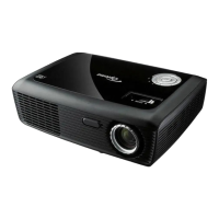
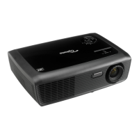
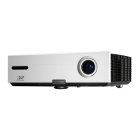
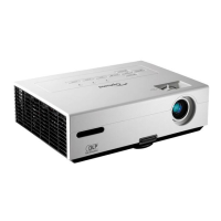
Lists and compares part numbers for ES529, EX539, and EW539 projectors.
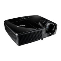
Provides a brief overview of the projector's key features and specifications.
Details the supported computer resolutions and signal timings for VGA modes.
Details supported computer resolutions and signal timings for XGA, HD, WXGA, SXGA, HDTV, MAC modes.
Details supported MAC resolutions and signal timings for MAC LC, MAC II, MAC 16", MAC 19", MAC G4.
Lists necessary tools and provides a general overview of the projector for disassembly.
Identifies and describes the key connectors on the projector's main board.
Explains the procedure for adjusting the projection lens rod for image alignment.
Guides users on how to reset the lamp usage hour counter after replacement.
Interprets various LED status indicators to diagnose projector issues.
Outlines troubleshooting steps for common projector symptoms like auto shut down or image abnormalities.
Provides steps to recover or reset the administrator password if forgotten.
Explains how to enter and exit the projector's service mode for advanced functions.
Details the process for resetting the fan's Revolutions Per Minute (RPM) value.
Specifies the test patterns and criteria for evaluating image quality defects.
Outlines which projector components are checked or updated during various inspection procedures.
Describes settings and considerations for connecting the projector to a PC.
Procedure and criteria for inspecting and testing for bright pixels on the screen.
Procedure and criteria for inspecting and testing for dark pixels on the screen.
Procedure and criteria for inspecting and testing for bright blemishes on the screen.
Procedure and criteria for inspecting and testing for dark blemishes on the screen.
Step-by-step guide for performing Analog-to-Digital Converter (ADC) calibration.
Details how to measure and verify the projector's brightness, contrast, and uniformity.
Lists required software and hardware components for system firmware upgrades.
Instructions on how to put the projector into firmware update mode.
Guide on how to verify the currently installed system firmware version.
Introduces the process for upgrading the 8051 microcontroller firmware.
Lists required hardware and software for the 8051 firmware upgrade.
Detailed steps for performing the 8051 firmware upgrade using specific tools.
Guide on how to verify the currently installed 8051 firmware version.
Details the procedure for upgrading the Extended Display Identification Data (EDID).
Illustrates an exploded view of the projector's components.
Provides a detailed list of projector parts from item 1 to 29.
Provides a detailed list of projector parts from item 30 to 38.
Shows exploded view and part numbers for the blower module assembly.
Shows exploded view and part numbers for the top cover module assembly.
Lists specific part numbers for the top cover module.
Shows exploded view and part numbers for the fan shielding module assembly.
Shows exploded view and part numbers for the bottom cover module assembly.
Lists specific part numbers for the bottom cover module.
Shows exploded view and part numbers for the engine module assembly.
Lists specific part numbers for the engine module.
Shows exploded view and part numbers for the color wheel module assembly.
Illustrates the process and components involved in carton packing.
Lists specific parts and labels used in carton packing from item 1 to 27.
Lists specific parts and labels used in carton packing from item 28 to 33.
Explains the format and meaning of projector serial numbers.
Defines the structure and components of the PCBA (Printed Circuit Board Assembly) code.
| Brightness | 2800 ANSI Lumens |
|---|---|
| Contrast Ratio | 15, 000:1 |
| Weight | 2.35 kg |
| Dimensions | 286 x 192 x 97 mm |
| Throw Ratio | 1.97 - 2.17:1 |
| Keystone Correction | ± 40° Vertical |
| Zoom Ratio | 1.1x |
| Aspect Ratio | 4:3 / 16:9 |
| Display Technology | DLP |
| Inputs | HDMI, VGA |
| Outputs | VGA, Audio |
| Power Consumption | <0.5W (Standby) |