Do you have a question about the Optoma EX762 and is the answer not in the manual?
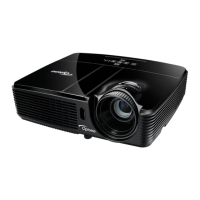
Detailed technical specifications and features of the projector.
Lists tools and components required for disassembly procedures.
Steps to remove the projector's lamp cover assembly.
Steps to detach the projector's lamp module.
Steps to detach the projector's top casing.
Procedure to remove the main electronic circuit board.
Procedure to remove the projector's engine assembly.
Procedure to remove the DMD chip and its associated board.
Procedure to remove the LVPS module and interlock switch.
Steps to detach the projector's lamp driver board.
Procedure for adjusting the rod mechanism for image alignment.
Steps to reset or update the projector's lamp usage hour.
Explains projector status codes based on LED indicator lights.
General troubleshooting steps for common projector issues.
Instructions on how to enter and navigate the projector's service mode.
Specifies environmental conditions and test patterns for evaluation.
Steps for testing video signal performance across different inputs.
Procedure for calibrating Analog-to-Digital Converter for video signals.
Procedures for measuring optical performance parameters like brightness.
Steps for testing and verifying the projector's network connectivity.
Miscellaneous functional checks and inspection points.
Covers equipment, setup, and procedure for system firmware updates.
Details steps for upgrading firmware via the 8051 microcontroller.
Covers network setup and procedures for firmware updates.
Explanation of Extended Display Identification Data and its purpose.
Steps to set up the EDID upgrade process using a VGA connection.
Steps to set up the EDID upgrade process using an HDMI connection.
Visual diagram showing the projector's internal components and their layout.
Explanation of the projector's serial number format and its components.
Explanation of the Printed Circuit Board Assembly (PCBA) code structure.
| Matrix size | 0.55 \ |
|---|---|
| Number of colors | 1.073 billion colors |
| Projection distance | 1.2 - 12 m |
| Vertical scan range | 25 - 85 Hz |
| Horizontal scan range | 15 - 91 kHz |
| Projection technology | DLP |
| Contrast ratio (typical) | 3000:1 |
| Screen size compatibility | 0.78 - 9.38 \ |
| Projector native resolution | XGA (1024x768) |
| Keystone correction, vertical | -40 - 40 ° |
| Interface | RS232, RJ45 |
| Resolution | 1600 x 1200 pixels |
| Aspect ratio | 4:3, 16:9 |
| Dimensions (WxDxH) | 324 x 234 x 97 mm |
| Power requirements | 100 - 240V, 50 - 60Hz |
| Throw ratio | 1.6 - 1.92:1 |
| Focal length range | 18.2 - 21.8 mm |
| Service life of light source | 3000 h |
| RMS rated power | 8 W |
| Video formats supported | Not supported |
| Serial interface type | RS-232 |
| USB 2.0 ports quantity | USB 2.0 ports have a data transmission speed of 480 Mbps, and are backwards compatible with USB 1.1 ports. You can connect all kinds of peripheral devices to them. |
| VGA (D-Sub) ports quantity | 3 |
| Noise level | 29 dB |
| Product type | Standard throw projector |
| Cable lock slot type | Kensington |
| Power consumption (standby) | 1 W |
| Power consumption (typical) | 314 W |
| Operating temperature (T-T) | 5 - 40 °C |
| Operating relative humidity (H-H) | 0 - 85 % |
| Weight | 2900 g |
|---|