OPTIMOD-FM 8500 TO 8600 UPGRADE INSTRUCTIONS
7
b) Orient the DSP board over the mounting points and fasten using the screws
reserved above.
c) Reconnect all cables to the DSP board.
d) Check all internal connections carefully for any loose or partially seated
connections.
e) Before replacing the top cover, test the installation to verify that the 8500
is properly recognizing the new circuit board that you just added.
Apply power to 8500. During the boot-up process, observe the front-panel
power LED. If the LED blinks RED, immediately disconnect power from
8500. Refer to Table 4-1 on page 4-10 of the 8500 V3.0 Operating Manual
for a table of blink codes for the power monitor LED. Then carefully review
all steps of these instructions without skipping steps. Normal operation is
indicated when the LED shows steady GREEN color.
NOTE: It is normal for a “DSP0 init failed” error message to appear. This
message will no longer appear after the 8600 software upgrade.
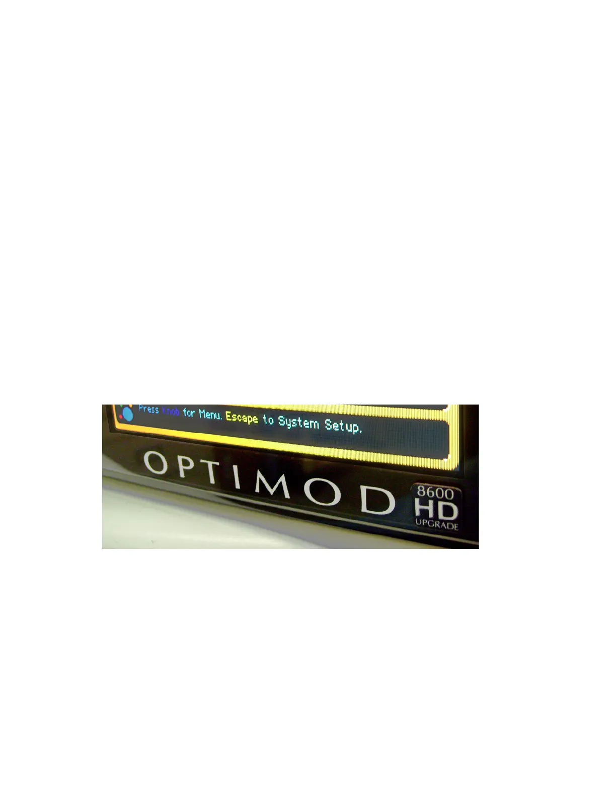
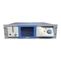
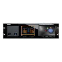
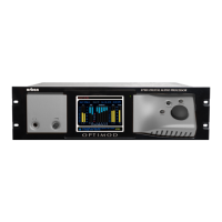
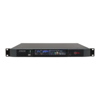
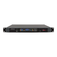
5. Apply upgrade stickers to the converted unit.
Your kit contained two upgrade stickers, one for the front panel and one
for the rear panel. Please affix them to your Optimod according to the
photos below:





 To Next Page