6-24
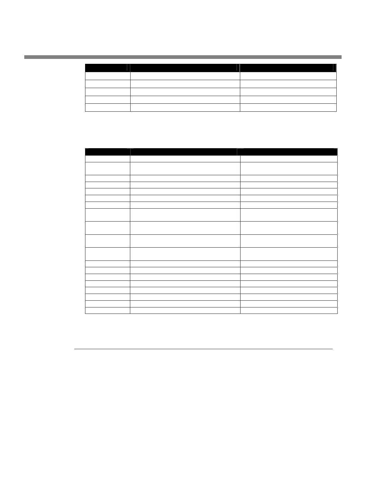
TECHNICAL DATA ORBAN MODEL 5700i
COMPOSITE/SCA DAUGHTERBOARD
PART # DESCRIPTION COMPONENT IDENTIFIER
20129.604.01 RESISTOR 0805 604 Ω 1% 1/8W R5, R6, R7, R8, R9, R10
20130.210.01 RESISTOR 1/8W 1% 2.10K 0805 R3, R4
20130.348.01 RESISTOR 1/8W 1% 3.48K 0805 R13, R14, R15, R16
20128.075.01 RESISTOR 75 Ω 1% 0805 R11, R12
Display Board
PART # DESCRIPTION COMPONENT, IDENTIFIER
25127.000.01 LED T1 3MM BLUE RND CR11, CR12, CR13, CR14, CR15
25174.000.01 LED ARY 10 BLUE CR1, CR2, CR3, CR4, CR5, CR6,
CR7, CR8, CR9, CR16
27379.010.01 CONNECTOR RCPT .100 1X10 GLD P1, P4
27380.010.01 CONNECTOR HEADER .100 1X10 GLD J1, J4
68006.000.02.1 WI FRT-BACK COMBO
27380.020.01 CONNECTOR HEADER .100 1X20 GLD J2, J3,
27379.020.01 CONNECTOR RCPT .100 1X20 GLD P2, P3
27403.006.01 CONNECTOR HSNG DOUBLE ROW 6
PIN
P202
20226.000.01 RESISTOR NET DIL 2% 100 OHM RP1, RP2, (DO, NOT, USE, DATE,
CODE, 9206)
21176.000.01 CAPACITOR CERAMIC 100V 47PF 5%
SMT
C9, C10, C11, C12, C13, C14, C15,
C16
21325.610.01 CAPACITOR 10UF 10% TANTALUM
3528
C1
24416.000.01 IC OCTAL D FLPFLP AC574 IC1, IC2
24638.000.01 IC OCTAL BUS TRANS W/3 IC8
25112.001.01 LED RED/GRN BI-CLR/POLR CR17
27420.002.01 CONNECTOR 2 PIN RIGHT ANGLE J5
26085.000.01 SW ROT VERT MNT 2 BIT S12
24417.000.01 IC OCTAL D FLPFLP AC374 IC3
43052.080.01 SASY CBL FLAT 21P 8" JP203
21139.000.01 CAPACITOR X7R 0.1UF 10% 0805 C2, C3, C4, C5, C6, C7, C8
Schematics and Parts Locator Drawings
These drawings reflect the actual construction of your unit as accurately as possible.
Any differences between the drawings and your unit are probably due to product
improvements or production changes since the publication of this manual.
If you intend to replace parts, please read page 6-16. Please note that because sur-
face-mount parts are used extensively in the 5700i,
few parts are field-replaceable.
Servicing ordinarily occurs by swapping circuit board assemblies. However, many vul-
nerable parts connected to the outside world are socketed and can be readily re-
placed in the field.

 Loading...