OPERATIONAL INSTRUCTIONS
LOAD ADJUSTMENT
There is a DAMPER(42) built into the RIGHT FAN
SHROUD(43). Move the Indicator in the DAMPER(42) to point to
the numbers on the RIGHT FAN SHROUD(43) to adjust the
load. There are settings from 1 to 9. Setting #1 will provide the
lowest resistance. Setting #9 will provide the highest resistance.
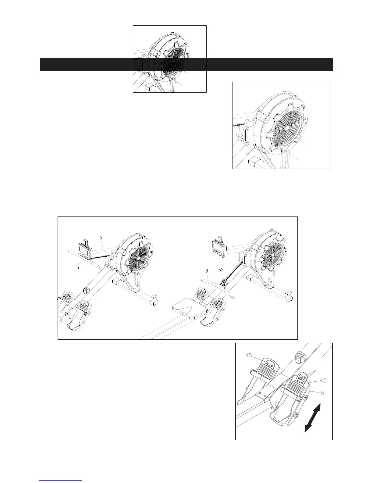
HANDLEBAR POSITION
The HANDLEBAR(3) can be placed on the hook in the CONSOLE MONITOR POST(6), refer to
illustration A. Or, you can place the HANDLEBAR(3) on the HANDLEBAR HOLDER(52) as shown in
illustration B.
PEDAL CAP ADJUSTMENT
The position of the FOOT PEDAL(45) can be adjusted. Refer to
the illustration. Pull the FOOT PEDAL(45) out from the two
bulges in the PEDAL SUPPORT PLATE(5), then lower or
raise the FOOT PEDAL(45) to the desired position. Lock the
FOOT PEDAL(45) in position by pressing the adjustment holes
of the desired position onto the two bulges.
Refer to the numbers on the FOOT PEDAL(45) to make sure that
FOOT PEDAL(45) are adjusted on the same position on both
sides.
Bulges
 Loading...