Page
09
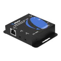
Operation Controls and
Functions & IR Pin Denition
No. Name Function Description
1.
CAT IN
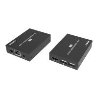
Connect a CAT 6/7 cable. The other end connects to the Trans-
mitter
2.
IR OUT
Connect the IR Blaster cable
3.
IR IN
Connect the IR Receiver cable
4.
HDMI OUT
Connect a display device such as TV, Monitor, etc.
5.
Power LED
The Green LED will light up when Receiver is powered on.
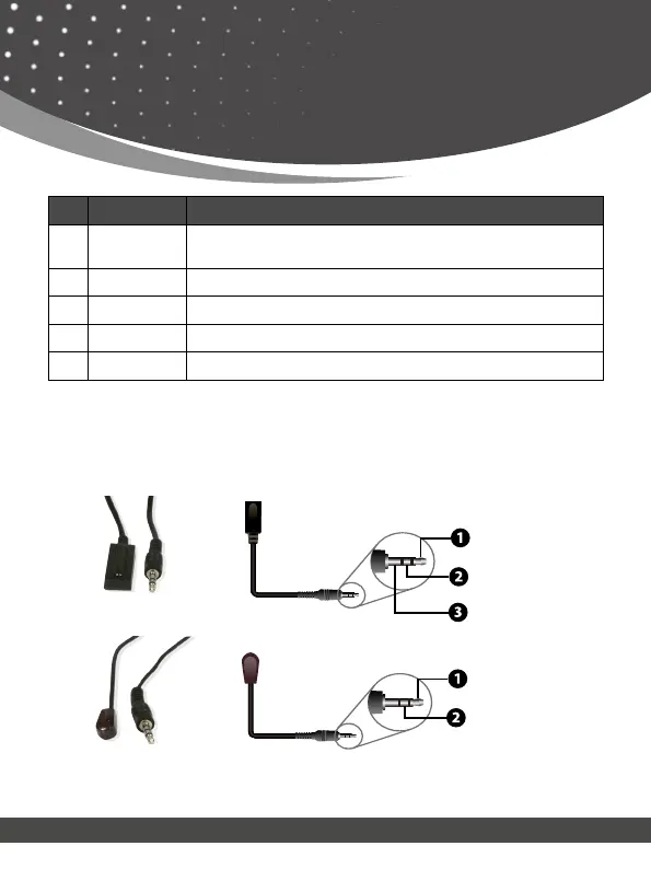
IR Receiver
IR Signal
Power
Grounding
IR RECEIVER
IR BLASTER
IR Blaster
IR Signal
Power
IR Pin Denition