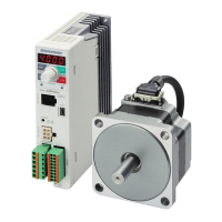
Do you have a question about the Oriental motor BLE2 Series and is the answer not in the manual?
Conditions to avoid for safe operation of the driver.
Safety precautions for maintenance and inspection.
Warnings against unauthorized repair or modification.
Further handling precautions, especially regarding semiconductor elements.
Precautions for safe installation and mounting.
Safety precautions for grounding and power supply connections.
Safety precautions during motor operation, including temperature.
Identifies and describes the parts of the driver.
Specifies ideal locations and conditions for driver installation.
Explains methods for installing the driver, including clearances.
How to connect the power supply to the driver.
How to connect the motor and driver using connection cables.
Proper grounding procedures for safety and product protection.
Measures to prevent damage from static electricity.
How to connect input and output signals to the driver.
Detailed pin assignments for the I/O signals connector.
Connecting external devices for analog settings.
How to connect the USB cable for PC communication.
How to connect the regeneration resistor for heavy loads.
Details on connecting the regeneration resistor.
Illustrates the wiring for sink logic with internal power.
Illustrates wiring for sink logic with external power.
Illustrates wiring for source logic with external power.
Examples of I/O signal connections with controllers.
Lists and describes all input and output signals.
How to set up to 16 operation data points.
How to set rotation speed using the operation panel.
Steps to set speed using external potentiometer or DC voltage.
How to limit motor output torque.
How to set accel/decel times to prevent load shock.
How to operate and stop the motor using FWD/REV inputs.
Identifies and explains operation panel components.
Describes the four available operation modes.
Details what information can be monitored on the display.
How to check and reset alarms.
How to check input/output signal status.
How to set up to 16 operation data values.
How to set various parameters using IDs.
Explains parameter IDs and how to input them.
How to check I/O signals and electromagnetic brake.
Detailed explanation of the I/O test mode.
How to lock/reset the operation panel settings.
Periodic inspection items for the motor and driver.
Troubleshooting steps when the motor fails to operate.
Troubleshooting for issues with rotation speed display.
Troubleshoot when 'Err' is shown and settings fail.
Steps to fix incorrect rotation direction.
How to address unstable motor movement or vibration.
Methods to reset generated alarms.
Specific steps for resetting via ALARM-RESET input.
Lists common alarms, causes, and remedies.
Cause and remedy for main circuit overheat alarm.
Cause and remedy for overvoltage alarm.
Cause and remedy for undervoltage alarm.
Cause and remedy for sensor error alarm.
Cause and remedy for main circuit output error.
Cause and remedy for overload alarm.
Cause and remedy for overspeed alarm.
Cause and remedy for EEPROM error.
Cause and remedy for sensor error at power-on.
Lists electrical and performance specifications for motors.
Methods for EMC-compliant installation and wiring.
| Brand | Oriental motor |
|---|---|
| Model | BLE2 Series |
| Category | Engine |
| Language | English |


 Loading...