-
18
-
3 Connection
■
Power supply capacity
Actuator model
Input power
supply voltage
Power supply current capacity
Electromagnetic
brake type
Without
electromagnetic brake
ELS2
,
ELF2
,
ELC2
DC24 V±10%
1.0 A
EZS3
1.7 A 1.6 A
ELS4
,
ELF4
,
ELX4
,
ELC4
,
EZS4
1.7 A 1.6 A
ELS6
,
ELF6
,
ELX6
,
ELC6
,
EZS6
4.0 A 3.7 A
3.2 Connecting the I/O signals
Connect to the I/O connector using the included I/O cable (AWG28: 2 m [6.6 ft.]) or shielded I/O cable
(AWG26).
Note
Insert the connector so that the brown lead wire faces the front panel side.
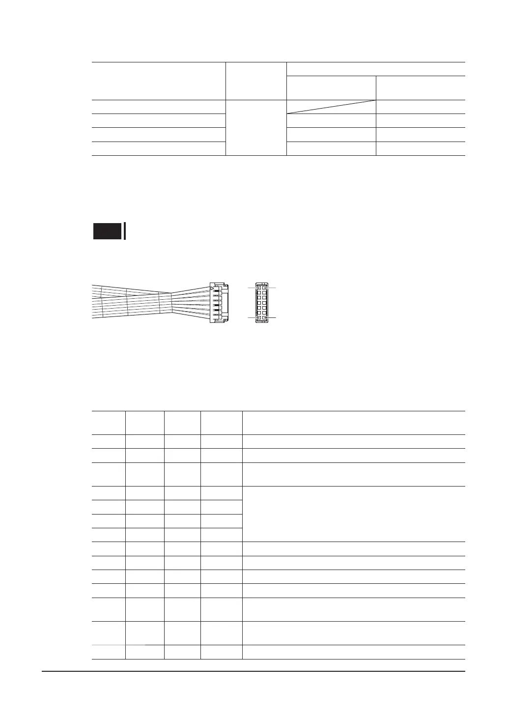
■
Connector pin assignments of I/O cable
B1
B7
A1
A7
I/O cable connector
•
Housing: DF11-14DS-2C (Hirose Electric Co., Ltd.)
•
Contact: DF11-2428SC (F) (Hirose Electric Co., Ltd.)
The following signals are assigned to the I/O with the factory settings. If the data editing software
EZED3
or accessory programming console
MPC10
(sold separately) are used, the assigned signals can
be changed.
Pin No.
Terminal
name
Wire
color
Signal
name
Description
A1 COM1 Brown COM1 Input signal common
A2 IN1 Red HOME Start signal for return-to-home operation.
A3 IN2 Orange FREE
The motor current is turned off and the electromagnetic
brake is released.
A4 − Yellow +FP-5V
Input pulse signals
A5 − Green −FP
A6 − Blue +RP-5V
A7 − Purple −RP
B1 COM2 Brown COM2 Output signal common
B2 IN3 Red RETURN Start signal for return operation.
B3 IN4 Orange SET-P This is a signal to set the electrical home position.
B4 OUT1 Yellow S_MOVE This signal is output while the actuator operates.
B5 OUT2 Green
S_
MTEMP
This signal is output when the motor temperature exceeds
the set value of the "motor warning temperature."
B6 OUT3 Blue
S_
DTEMP
This signal is output when the driver temperature exceeds
the set value of the "driver warning temperature."
B7 OUT4 Purple ALM This signal is output when an alarm is generated.
 Loading...