A1250 AMPLIFIER INSTALLATION USER MANUAL
13
12
A1250 AMPLIFIER INSTALLATION USER MANUAL
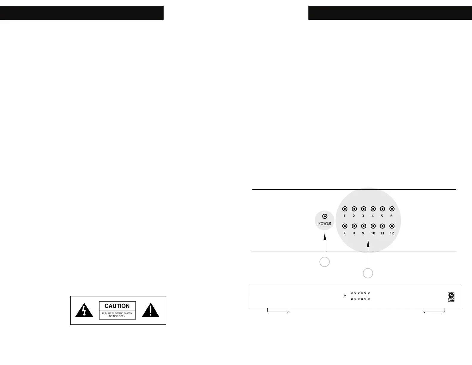
The amplifier has small LEDs on the front panel to indicate the power state and
channel status. The Power LED lights up to indicate the amplifier is ON. There is
a LED indicating the channel state. Use the LEDs to identify and trouble shoot
channels that are not working. If a channel is in fault mode, power down the amp,
identify and fix the issue. When complete, power up the amp again to check the
issue has been resolved.
• Power ON = Blue
• Power OFF = Red
• Channel ON = Blue
• Channel Fault = Red
• Channel Fault conditions are due to : shortcircuit, thermal, or overload failures.
All connections and switching must be done with the amplifier
turned o. Connect the power cord last to ensure that the amplifier is o during
all the connections and set up.
All RCA audio connections on the amplifier are gold-plated, for superior, non-
corrosive, and long-lasting performance.
Use high-quality RCA cables that feature low impedance with adequate shielding
and high-quality connectors. Using removable speaker connectors ensures easier
wiring, faster installation, and troubleshooting.
A detachable fused EIC grounded power cable defeats, noise, simplifies
troubleshooting and adds protection needed.
Some stereo zones use 1/8” stereo jacks instead of RCA connections.
The smaller space taken up by the stereo connection oers an in and out
preamplifier connection for adding additional amplifiers, speakers or subwoofers
in each zone.
Use up to 14 gauge stranded two-conductor speaker wire. Connect the
appropriate conductor to each screw terminal, observing correct polarity.
TO REDUCE THE RISK OF ELECTRIC SHOCK, DO NOT
REMOVE COVER OR BACK. NO USER-SERVICEABLE
PARTS INSIDE. REFER SERVICING TO AUTHORIZED
SERVICE PERSONNEL.
CAUTION: WARNING:
TO PREVENT FIRE OR SHOCK HAZARD, DO NOT
EXPOSE THIS APPLIANCE TO RAIN OR MOISTURE. THE
APPLIANCE SHALL NOT BE EXPOSED TO DRIPPING OR
SPLASHING. NO OBJECTS FILLED WITH LIQUIDS SHALL
BE PLACED ON THE APPLIANCE.
100-120 V ~ 60Hz / 220-240V ~ 50Hz 600W
FUSE T10AL / 250V
LEVEL
ZONE 6
(L)+
- (R)
POWER
MODE
ON
AUTO
TRIGGER
DC 12V
Manufactured in China
LEVEL
ZONE 5
(L)+
- (R)
LEVEL
ZONE 4
(L)+
- (R)
LEVEL
ZONE 3
(L)+
- (R)
LEVEL
ZONE 2
(L)+
- (R)
LEVEL
ZONE 1
(L)+
- (R)
SPDIF IN
L
R
IN
LOOP OUT
POWER
1 2 3 4 5 6
7 8 9 10 11 12
B
A