Page 12 / 36
Hartley and Sugden
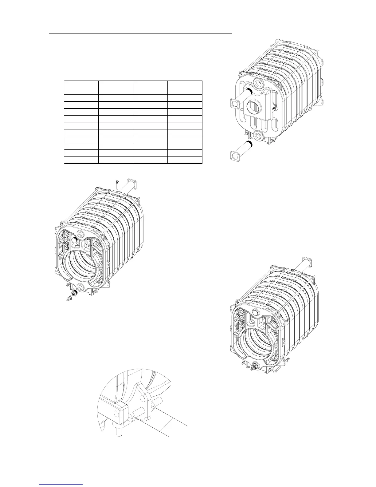
18. Place the tube of 3s with its flange on the boiler outlet. According
to t he configurations, there might be an inlet water injector, this
one is always pl aced on the boiler inlet. If no inlet water injector
in t he configuration, place the second tube of 3s with its flange on
the boiler inlet.
19. Place the p lunger in the for es een opening on the rear section, place a
plug with hexagon head of 2s on the front sect ion in upper part and a
fittingreductionfrom2s to 3/4s aswellasa draincock 3/4s in lower part.
20. Screw the 2 hinges into the tapped holes in the front section ( left
or right side according to the dir ection opening selected) . Respect
the distance of 60mm as showed on fig 21b . then pl ace the washer
M16 and the nut M16 to block la rotation of the hinge.
20b.
60
Typ e
Pipe injectors
L=70mm
Pipe injectors
L=140mm
Pipe injectors
L=190mm
122
132
241
242 X
234 X
244 X
335 X
345 X
355 X
455 X