IG-267-EN versión 01; 07/04/2017
47
General Instructions
ekor.rpa
Detection, automation and control functions
5.3.3. Switch control statuses
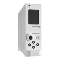
The switch control unit implemented in the ekor.rpa-100
system generates a series of signals which report its status.
These signallings are:
• Switch status: Indicates the current status of the switch:
open or closed.
• Opening correct by protection trip: Indicates that
the switch opening caused by protection tripping or
external tripping was correct.
• Opening failure by protection trip: Indicates that there
was an error in the switch opening caused by protection
tripping or external tripping.
• Opening correct by remote opening command:
Indicates that the switch opening caused by a remote
control order was correct.
• Opening failure by remote opening command:
Indicates that there was an error in the switch opening
caused by a remote control order.
• Correct closing by reclosing: Indicates that the switch
closing caused by a reclosing order was correct.
• Closing failure by reclosing: Indicates that there was
an error in the switch closing caused by a closing order.
• Correct closing by remote closing command: Indicates
that the switch closing caused by a remote control order
was correct.
• Closing failure by remote closing command: Indicates
that there was an error in the switch closing caused by a
remote control order.
5.4. Remote control
The ekor.rpa-100 units are fitted with a serial
communication port which can be used for telecontrol,
following standard RS-485, allowing connection of up to
a maximum of 32 units in a single bus. The 485 port has
a twisted pair connection. The Distribution or Transformer
Substation telecontrol terminal sends the encoded frames
for each of the ekor.rpa-100 units they are connected
to via the RS-485 bus. The communication between the
communications terminal and the dispatching centre
depends on the protocol used.
Some of the functions available through remote control are:
• Switch status display.
• Earthing switch display.
• Switch operation.
• Switch error monitoring.
• Coil monitoring.
• Phase and neutral current metering with module and
angle relative to VA.
• Phase and neutral voltage metering with module and
angle relative to VA.
• Active, reactive and apparent power metering.
• Energy metering.
• Display presence/absence of voltage in each phase A, B
and C.
• Display and set system parameters.
• Fault reports record.
• Event record.
• Time synchronisation.
• Error/alarm indications.
 Loading...