Do you have a question about the Ormazabal ekor.rpa Series and is the answer not in the manual?
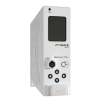
Overview of the ekor.rpa-100 series relays, covering microprocessor function, interfaces, and testing.
Details the main parts of the ekor.rpa-100 series: electronic relay, voltage and current sensors, auxiliary circuits.
Covers the unit's overall functionality validation and Ormazabal's R&D facilities (CIT).
Details communication ports (Ethernet, USB, RS-485) and protocols (MODBUS, PROCOME).
Enables remote visualization and operation of functional units in transformer and distribution substations.
Describes automatic line reclosing after overcurrent trips to restore power and reduce fault duration.
Details protective functions for lines using circuit-breakers, including various overcurrent and earth fault relays.
Details protection functions required for distribution transformers, dependent on power and responsibility.
Minimizes power outages by automatically transferring loads between incoming lines, improving service continuity.
Detects low-value fault currents in isolated or resonant earthed neutral networks using Function 59.
Enables sending outgoing information to SCADA via web or MODBUS-TCP for monitoring and control.
Analyzes non-technical losses by using MV energy metering to uncover potential billing errors.
Details the unit's four current and three voltage inputs for signal conditioning and calculation.
Monitors single-phase and three-phase active, reactive, and apparent power, and power factor.
Features an active and reactive energy meter, accumulating 100 power measurements for three single-phase and one three-phase meter.
Details phase, neutral, and sensitive neutral overcurrent units, including timed and instantaneous types.
Describes instantaneous overcurrent unit start-up, reset conditions, and tripping time settings.
Detects low-value phase-to-earth fault currents using toroidal-core transformers for networks with sensitive neutral.
Combines overcurrent units with directional settings to decide on tripping based on fault direction.
Determines fault direction using angular criterion, with settings for characteristic angle and minimum voltage.
Uses angular or wattmetric criteria to determine neutral fault direction, with settings for neutral power and voltage.
Protects lines and transformers against thermal overloads not detected by conventional units.
Calculates thermal capacity based on phase currents using a formula that accounts for cooling and heating constants.
Details the thermal unit's operation for alarm and trip signals, including settings for rise constants, cooling, and trip levels.
Illustrates the block diagram for the thermal image unit, showing alarm, temporize, and trip signal generation.
Detects open lines that conventional protection cannot identify, by monitoring sequence currents.
Explains the calculation of sequence currents (positive, negative, zero) used for broken conductor detection.
Covers various voltage protection units including overvoltage, undervoltage, and neutral protection types.
Details timed overvoltage units for phase protection, including start-up, curve types, and tripping times.
Details instantaneous overvoltage units for phase protection, including start-up, fixed time, and working voltage.
Details timed overvoltage units for neutral protection, including start-up, curve types, and tripping times.
Details instantaneous overvoltage units for neutral protection, including start-up, fixed time, and working voltage.
Details timed undervoltage units for phase protection, including start-up, curve types, and tripping times.
Details instantaneous undervoltage units for phase protection, including start-up, fixed time, and working voltage.
Illustrates the block diagram for voltage units, showing magnitude measurement, time counting, and trip logic.
Blocks overcurrent units during transformer energization by monitoring fundamental and second harmonic current.
Details the functionality of the second harmonic blocking unit, including settings for thresholds and cross-blocking.
Presents the block diagram for the second harmonic blocking unit, illustrating signal generation and logic.
Blocks protection units when line current exceeds set values, entrusting protection to fuses above the threshold.
Enables automatic line reclosing after overcurrent trips to restore power and reduce fault duration.
Details the recloser's operation, cycle, attempts, and independent timing for phase and neutral faults.
Covers settings for enabling, number of reclosings, timing, permissions, and safety times.
Describes recloser statuses: manual/automatic, blocked/unblocked, standby, under way, final trip, and reclosing order.
Detects voltage presence or absence in lines per phase, based on voltage levels and time thresholds.
Explains how the automation detects voltage presence/absence based on levels, hysteresis, and timing.
Covers settings for enabling, line voltage, presence/absence levels, hysteresis, and timing parameters.
Enables operation and monitoring of the cubicle switch, including switch error automation.
Describes the unit's inputs/outputs for switch operation and monitoring, and switch error automation.
Defines settings for switch opening and closing failure times to ensure correct switchgear operation.
Reports statuses like switch open/closed, correct/failed opening/closing, and reclosing order correctness.
Details telecontrol via RS-485, listing available functions like status display, metering, and parameter settings.
Describes sensors designed for optimal adaptation to digital equipment, highlighting advantages like low volume and improved accuracy.
Provides detailed characteristics of phase current toroidal transformers, including ratio, metering class, and thermal current.
Explains two connection methods for transformers: with or without a zero-sequence toroidal current transformer.
Covers voltage sensors including bushing-integrated dividers and optional external sensors.
Describes voltage detection using capacitor dividers in cubicle bushings, detailing precisions and standards.
Details the ekor.evt-c sensor, its components, voltage measurement capabilities, and BNC outputs for connectivity.
Lists rated values for power supply, current inputs, voltage inputs, accuracy, frequency, outputs, and communication ports.
Specifies protection grades, dimensions, weight, and connection types for the equipment.
Details insulation resistance and dielectric strength tests performed according to IEC standards.
Covers EMC performance, including radioelectrical interference, immunity tests (ESD, RF, transients, etc.), and conducted interference.
Outlines climatic tests for damp heat, dry heat, cold, and temperature variation according to IEC standards.
Details mechanical tests including vibration and IP protection grade according to IEC and ETSI standards.
Specifies power tests for cable making/breaking and load making/breaking according to IEC standards.
Confirms product compliance with EU directives on electromagnetic compatibility and IEC standards.
Describes ekor.rpa-110 and ekor.rpa-120 models (v-type and p-type), their interconnection, configuration, and optional features.
Details the ekor.rpa-110 unit's multilevel overcurrent protection, recloser, and voltage detection functions.
Details the ekor.rpa-120 unit's functions, including directional units, broken conductor, thermal image, and voltage protection.
Compares ekor.rpa-110/120 models for circuit-breaker (v-type) and fuse (p-type) cubicles, detailing functions and applications.
Explains how to select the correct ekor.rpa-100 unit based on installation characteristics using a configurator table.
Details the design and function of v-type units for circuit-breaker cubicles, focusing on protection and quick trip order.
Explains the main function of v-type units to protect lines and transformers, ensuring safety in the tripping chain.
Defines the standard physical inputs and outputs for v-type units, isolated from other circuits.
Describes the installation of electronic relays, sensors, and terminal blocks for v-type units within a cubicle.
Covers commissioning and maintenance checks for v-type units, detailing primary current circuit tests and cable compartment access.
Details the design and function of p-type units for fuse protection cubicles, focusing on transformer protection.
Explains p-type unit function for transformer protection in fuse cubicles, handling overcurrents and fuse clearing.
Defines the standard physical inputs and outputs for p-type units, isolated from other circuits.
Guides the selection of protection parameters for ekor.rpa-110/120-p units in fuse protection cubicles.
Describes the installation of p-type units, noting differences in terminal blocks compared to v-type units.
Covers checks and maintenance for p-type units, emphasizing careful current transformer installation to avoid false trips.
Details system information and settings classified into general, protection, automation, and local communication.
Covers settings for phase timed overcurrent units, including enable, start-up, curve type, index, fixed time, and torque control.
Covers settings for the second phase timed overcurrent unit, including enable, start-up, curve type, index, fixed time, and torque control.
Covers settings for phase instantaneous overcurrent units, including enable, start-up, unit timing, and torque control.
Covers settings for neutral timed overcurrent units, including enable, start-up, curve type, index, fixed time, and torque control.
Covers settings for the second neutral timed overcurrent unit, including enable, start-up, curve type, index, fixed time, and torque control.
Covers settings for neutral instantaneous overcurrent units, including enable, start-up, unit timing, and torque control.
Covers settings for sensitive neutral timed overcurrent units, including enable, start-up, curve type, index, fixed time, and torque control.
Covers settings for the second sensitive neutral timed overcurrent unit, including enable, start-up, curve type, index, fixed time, and torque control.
Covers settings for sensitive neutral instantaneous overcurrent units, including enable, start-up, unit timing, and torque control.
Covers settings for phase directional units: characteristic angle, minimum voltage, and indeterminate zone.
Covers settings for neutral directional units: characteristic angle, minimum power, minimum voltage, and indeterminate zone.
Covers settings for sensitive neutral directional units: characteristic angle, minimum power, minimum voltage, and indeterminate zone.
Covers settings for the broken conductor unit: enable, base current, start-up, unit timing, and current thresholds.
Covers settings for second harmonic blocking: enable, thresholds, cross-blocking, current thresholds, and block time.
Covers settings for timed undervoltage units: enable, working voltage, start-up, curve type, index, and fixed time.
Covers settings for instantaneous undervoltage units: enable, working voltage, start-up, and fixed time.
Covers settings for timed overvoltage units: enable, working voltage, start-up, curve type, index, and fixed time.
Covers settings for instantaneous overvoltage units: enable, working voltage, start-up, and unit timing.
Covers settings for timed neutral overvoltage units: enable, start-up, curve type, index, and fixed time.
Covers settings for instantaneous neutral overvoltage units: enable, start-up, and unit timing.
Covers settings for the thermal image unit: enable, rise constant, cooling constant, alarm, trip, reset levels, and rated current.
Configures automation functions including recloser, switch error, and voltage presence/absence.
Covers settings for recloser automation: enable, number of reclosings, timing, permissions, and safety times.
Covers settings for switch error automation: opening and closing failure times.
Covers settings for voltage presence/absence automation: enable, line voltage, presence/absence levels, hysteresis, and timing.
Configures communication parameters for RS-485 and virtual COM ports, including protocols and settings.
Details communication parameters for RS-485 port: peripheral number, baud rate, parity, length, stop bits, and protocol.
Details communication parameters for the virtual COM port, including peripheral number and protocol.
Covers settings for date and time: day, month, year, hour, minute, and second.
Details IP address settings for local and remote communication, including IP, mask, and gateway.
Describes the system's storage of fault records, their text format, filename convention, and data capture logic.
Explains how new fault reports are generated, stored, and closed based on unit start-up and tripping orders.
Details the five functional parts of a fault report: system info, fault summary, protection status, switch current, and event record.
Lists available signals for log records, categorized by unit type/group and subgroup, detailing their status.
Describes the storage and classification of events, including functional groups and structure for filtering and analysis.
Explains how to check and configure parameters via the web server, detailing its characteristics and access methods.
Details local and remote access to the web server, including user roles, default passwords, and connection options.
Describes parameter management via the web server, covering tabs for maintenance, logs, configuration, and leaving the session.
Covers downloading different logs: substation events, alarms, faults, and software version changes.
Explains how to configure substation parameters: protection settings, IP addresses, passwords, and automation menus.
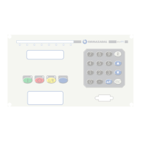
Details the electronic relay's keyboard and display for setting and viewing parameters, organized in a tree structure.
Explains the keyboard layout and navigation through the display's tree structure for accessing data screens.
Illustrates the main browsing branch for the display, showing general screens for user settings, clock, status, and meterings.
Describes the structure of screens for user settings, mirroring the XML settings file organization.
Shows the screen structure for date and time settings, illustrating navigation for setting year, month, day, hour, minute, second.
Illustrates the screen structure for various system statuses, including voltage, automation, and switch states.
Details the screen structure for the last 10 reports stored in the system, showing fault information on priority screens.
Presents the screen structure for system meterings, visualizing current, voltage, power, energy, and thermal capacity.
Shows the screen structure for system information, including model, range, type, firmware version, and logic ID.
Lists and explains error codes used to warn users about system anomalies, providing unique numbers for identification.
Describes how the device shares files via USB memory for configuration updates, fault reports, and metering display.
Explains how to connect to the system via USB memory, detecting the new drive and accessing files.
Details interacting with the USB interface using file extract/import commands and the priority order of tasks.
Explains the use of the ekor.soft-xml utility for browsing, displaying, editing, and loading system settings via USB.
Describes the RS-485 twisted pair cable connection for telecontrol, detailing port configuration parameters.
Explains the MODBUS slave configuration in RTU mode for the COM0 port, highlighting advantages over ASCII mode.
Details the MODBUS data reading question and response frames, including address, function, and data parameters.
Details the MODBUS data writing question and response frames for single register updates.
Explains MODBUS parameter protection using passwords, error codes, and CRC generation for data integrity.
Provides a map of MODBUS addresses for information, system identifiers, and logic table identifiers.
Details MODBUS addresses for clock settings: year, month, day, time, minute, and second.
Details MODBUS address for user key access to settings with user privileges.
Details MODBUS addresses for commands and outputs, covering read/write operations for various signal groups.
Details MODBUS addresses for meterings and statuses: phase voltages, currents, powers, angles, and internal statuses.
Details MODBUS addresses for energy metering: three-phase and single-phase active and reactive energy, and total apparent power.
Details MODBUS address for thermal capacity metering.
Explains the PROCOME protocol implementation as a slave, covering initialization, control functions, and information exchange.
Describes PROCOME fixed-length frames for link level communication, including start, control, address, sum, and end fields.
Describes PROCOME application level ASDUs, including header structure and information object identifiers for data exchange.
Describes the Ethernet connection for web access via ETH0 and ETH1 ports, detailing default IP addresses.
Explains the use of a USB cable for connecting to the system, enabling maintenance operations without auxiliary power.
Shows the time-current characteristic curve for the IEC DT (Defined Time) protection function.
Shows the time-current characteristic curve for the IEC NI (Normally Inverse) protection function.
Shows the time-current characteristic curve for the IEC VI (Very Inverse) protection function.
Shows the time-current characteristic curve for the IEC EI (Extremely Inverse) protection function.
Shows the time-current characteristic curve for the IEC LTI (Long Time Inverse) protection function.
Shows the time-current characteristic curve for the IEC STI (Short Time Inverse) protection function.
Shows the time-current characteristic curve for the ANSI NI (Normally Inverse) protection function.
Shows the time-current characteristic curve for the ANSI VI (Very Inverse) protection function.
Shows the time-current characteristic curve for the ANSI EI (Extremely Inverse) protection function.
Shows the time-current characteristic curve for the ANSI LI (Long Time Inverse) protection function.
| Rated operational current | 5A |
|---|---|
| Rated frequency | 50/60 Hz |
| Rated voltage | 24-250V AC/DC |
| Operating temperature | -25°C to +70°C |
| Communication protocols | IEC 61850, Modbus RTU/TCP, DNP3 |
| Storage temperature range | -40°C to +85°C |
| Protection degree | IP20 |