IG-267-EN versión 01; 07/04/2017
36
Protection functions General Instructions
ekor.rpa
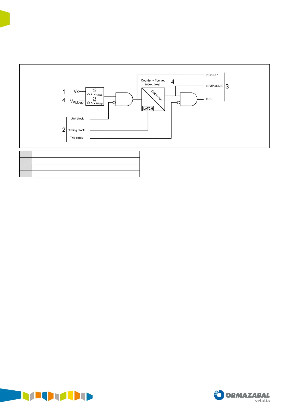
4.6.5. Block diagram
Any voltage unit complying with the diagram shown below.
1
Metering
2
Input signal
3
Output signal
4
Settings
Figure 4.13. Block diagram
The diagram represents, whenever the magnitude measured
in real time (Vx) is: a) higher in the case of overvoltage units:
59 or, b) lower in the case of undervoltage units: 27 than the
setpoint value (V
pick up
setting), a time counter counts down
(counter: ƒ (curve, index, time) tripping once completely
expired.
If the measured magnitude (Vx) drops (overvoltage units: 59)
or increases (undervoltage units: 27) over setpoint (V
pick up
),
the unit and the counter are reset, with the unit remaining idle
All the units generate the following signalling:
• Pick-up: Activated when the measured magnitude (Vx)
is higher (overvoltage units: 59) or below (undervoltage
units: 27) a setpoint (V
pick up
setting), and disabled when
the metering value is lower (overvoltage units: 59) or
higher (undervoltage units: 27) than the setpoint.
• Temporize: Activated when the time counter reaches
its end, and disabled when the metering value is lower
(overvoltage units: 59) or higher (undervoltage units: 27)
than the setpoint.
• Trip: Activated when the Temporize signal is activated,
and disabled when the metering value is lower
(overvoltage units: 59) or higher (undervoltage units: 27)
than the setpoint.
Moreover, the voltage units can be blocked by the
maximum current blocking unit detailed in the following
sections.
Moreover, the voltage units can be blocked in three different
ways:
• Unit Block: Blocks the unit, preventing start-up while
this input remains active.
• Timing Block: Freezes the time counter value while this
input is active.
• Trip Block: Allows the unit to advance, and blocks it
before the trip output.
 Loading...