IG-267-EN versión 01; 07/04/2017
68
Protection, metering and control models General Instructions
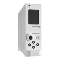
ekor.rpa
8.3.3. Fuse protection
The ekor.rpa-110/120-p unit is used for transformer
protection, and works in combination with the fuse
protection.
The process for choosing the protection parameters for the
ekor.rpa-110/120-p cubicle unit is as follows:
1. Determine the required fuse rating to protect the
transformer in accordance with the fuse table of each
cubicle family. Check the maximum and minimum
calibres in the (IG) for each cubicle system, in accordance
with the line voltage level where they are to be used.
2. Calculate the machine's rated current I
n
= S/√3 x U
n
.
3. Define the continuous overload level I>. Normal
values in transformers of up to 2000 kVA are 20 % for
distribution installations and 5 % for power generation
installations.
4. Select the transient overload curve. Coordination
between relay curves and LV fuses is performed with
the EI type curve.
5. Define the delay time in transient overload K. This
parameter is defined by the transformer’s thermal
constant. This way, the greater the constant, the longer
it takes for the transformer’s temperature to increase
under an overload condition; and therefore, the
protection trip can be delayed longer. The normal value
for distribution transformers is K = 0.2, which means
that it trips in 2 s if the overload is 300 % in the EI curve.
6. Short-circuit level I>>. The maximum value of
the transformer’s magnetisation current must be
determined. The current peak produced when a no-
load transformer is connected, due to the effect of a
magnetised nucleus, is several times greater than the
rated current. This peak value, up to 12 times the rated
value (10 times for more than 1000 kVA) has a very high
harmonic content, so its fundamental 50 Hz component
is much less. Therefore, a usual setting value for this
parameter is between 7 and 10.
7. Instantaneous timing T>>. This value corresponds
to protection trip time in the event a short-circuit
occurring. It depends on coordination with other
protections and the normal values are between 0.1
and 0.5 s. Whenever the short-circuit value is high, the
fuses will act in the time specified by their characteristic
curve.
8. Determine the current value in case of secondary three-
phase short-circuit. This fault must be cleared by the
fuses, and it corresponds with the intersection point’s
maximum value between the relay and the fuse curves.
If the intersection point is greater than the secondary
short-circuit value, the settings must be adjusted to
meet this requirement.
Example: When protecting a transformer with following
characteristics in a cgmcosmos cubicle system up to
24 kV:
a. Choice of fuse in accordance with IG-078.
Fuse 10/24 kV 125 A
b. Rated current.
I = S/√3 x U = 1250 kVA/√3 x 15 kV = 48 A
c. Continuous withstand overload 20 %.
I
n
x I> = 48 A x 1.2 = 58 A
d. Extremely Inverse Curve type. E.I.
e. Transient overload factor. K = 0.2
f. Short-circuit level. I> x I>> = 58 x 7 = 404 A
g. Instantaneous timing T>> = 0.4 s
h. Secondary short-circuit.
I
cs
= I
n
x 100/U
k
= 48 A x 100/5 = 960 A

 Loading...