IG-267-EN versión 01; 07/04/2017
107
General Instructions
ekor.rpa
Communications
Continuation
Address
(HEX)
Field Description Size Read/write
0 x 0A18 EB+ Active energy imported (in kWh) phase B 32 bits Read
0 x 0A1A EB- Active energy exported (in kWh) phase B 32 bits Read
0 x 0A1C QB1 Reactive energy Q1 (in kVArh) phase B 32 bits Read
0 x 0A1E QB2 Reactive energy Q2 (in kVArh) phase B 32 bits Read
0 x 0A20 QB3 Reactive energy Q3 (in kVArh) phase B 32 bits Read
0 x 0A22 QB4 Reactive energy Q4 (in kVArh) phase B 32 bits Read
0 x 0A24 EC+ Active energy imported (in kWh) phase C 32 bits Read
0 x 0A26 EC- Active energy exported (in kWh) phase C 32 bits Read
0 x 0A28 QC1 Reactive energy Q1 (in kVArh) phase C 32 bits Read
0 x 0A2A QC2 Reactive energy Q2 (in kVArh) phase C 32 bits Read
0 x 0A2C QC3 Reactive energy Q3 (in kVArh) phase C 32 bits Read
0 x 0A2E QC4 Reactive energy Q4 (in kVArh) phase C 32 bits Read
Table 12.12. Single-phase
Thermal capacity (from 0 x 0A80 to 0 x 0A9F)
Address
(HEX)
Field Description Size Read/write
0 x 0A80 T [tenths of %] Thermal capacity 32 bits Read
Table 12.13. Thermal capacity
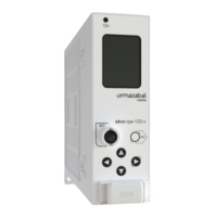
12.1.2. PROCOME protocol
The ekor.rpa-100 unit can be configured for the COM0
port communication protocol to be PROCOME. The system
therefore works as a PROCOME slave.
PROCOME is an asynchronous serial communication
protocol conceived for data transfer between control and
protection equipment in electrical installations, following
standards IEC 870-5.
The PROCOME implementation in the ekor.rpa-100 unit has
initialisation functions (without key) and control functions,
along with file transfer in order to exchange different types
of information:
• Inputs + digital statuses.
• Meterings.
• Settings files.
• Fault records
• Orders.
Link Level
The link layer follows the indications given about the
PROCOME protocol. These frames follow the T1.2 frames
standard of the IEC, 870-5-2. However, the length of the
address field of the equipment is 8 bits.
The value 0xFF in the addresses is reserved for broadcasting.
The fixed-length frames structure (without application
data) is as follows:
Oset Name Value Description
0
Start 0 x 10 Fixed-length frame start indication
1
Control 0 x 00 – 0 x FF Control word
2
Address 0 x 00 – 0 x FF Destination/source node address
3
Sum 0 x 00 – 0 x FF Sum of offsets 0 and 1 data (control and address)
4
End 0 x 16 End of frame indication
Table 12.14. Fixed length frames structure
 Loading...