IG-267-EN versión 01; 07/04/2017
71
General Instructions
ekor.rpa
Protection, metering and control models
8.3.4. Installation in a cubicle
The components of the ekor.rpa-110-p and ekor.rpa-120-p
units are, as with the ekor.rpa-110/120-v, the electronic
relay, voltage and current sensors, bistable tripping device
(binox), tripping coil and interconnection terminal block.
The main difference is that the circuit-breaker cubicle
has terminal block-52 (switch control terminal), while
the fuse protection cubicle has terminal block-R (fuse
status indication terminal block). Furthermore, the G-tests
terminal blocks are not included as a standard option in the
fuse-protected cubicle.
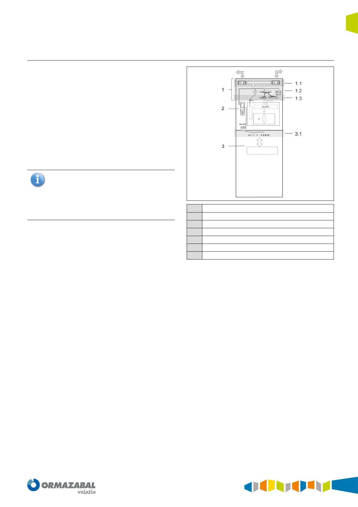
Installation by functional unit can be classified in the
following parts:
The description presented is for standard configuration.
Optionally, other configurations or test terminals can
be added, as well as positioning the unit in a control
box installed on the cubicle.
For further information or details on configurations
(schematic, etc.), contact Ormazabal's technical-
commercial department for your zone.
Release
I&V Sensors
1
Interconection terminal block
1.1
Power and communications bus
1.2
Relay terminal block
1.3
Cubicle terminal block
2
ekor.rpa-110-p or ekor.rpa-120-p electronic relay
3
Voltage and current sensors
3.1
Sensors interconnection
Figure 8.11. ekor.rpa installation
 Loading...