Do you have a question about the Orolia KANNAD 406 AF and is the answer not in the manual?
Overview of the COSPAS-SARSAT system for search and rescue operations.
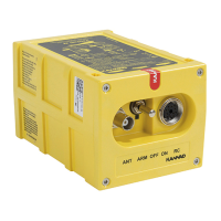
Introduces the KANNAD 406 series ELTs and their main components.
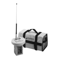
Details on ELT components: transmitter, bracket, remote control panel, and external antenna.
Covers mechanical design, general features, and compatibility lists for accessories.
Lists compatible external antennas for KANNAD 406 AF, AF-H, and AF(6D) models.
Explains transmitter functions, operating modes (Off, Armed, On), and endurance.
Describes ELT controls, indicators, buzzer, and electrical connections.
Details technical specs, activation, reset procedures, and self-test guidelines.
Covers ELT registration, programming, and bracket mounting requirements.
Provides installation directions for AF, AF-H, and AF(6D) models on different aircraft.
Steps for mounting the ELT, connecting antenna, and wiring control panel.
Guides through initial power-up, ELT, RCP, and transmission tests.
Explains self-test procedures, periodicity, and interpreting fault indicators.
Methods for diagnosing and resolving issues using visual indicators and fault codes.
Provides outline dimensions, drilling mask, and wiring diagram for the ELT system.
Shows dimensions and mounting details for ANT AV200, AV300, and ANT560 antennas.
Outlines periodic inspection checks and the overall maintenance schedule.
Mandatory conditions and requirements for replacing the ELT battery.
| Operating Temperature | -20°C to +55°C |
|---|---|
| Activation | Automatic or Manual |
| Frequencies | 406 MHz, 121.5 MHz |
| Power | 5W (406 MHz) |
| Battery Life | 6 years |
| Compliance | COSPAS-SARSAT |