PAGE: 106
MAR 30/2020
INSTALLATION MANUAL OPERATION MANUAL
KANNAD 406 AF / AF-H / AF (6D)
© 2020 Orolia S.A.S. All rigths are strictly reserved.
5. Electrical characteristics
Transmitter power supply: 3 x LiMnO
2
D type cells.
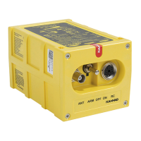
A. Electrical interface
When installed on board, the ELT has to be connected:
• to a Remote Control Panel via a DIN12 connector;
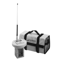
• to an outside antenna via a BNC connector.
The DIN12 connector is also used to connect a programming dongle, a CS144
interface or a programming and test equipment.
J1
This connector is dedicated for connection to the Remote Control Panel, to the
Programming or Maintenance Dongles, to the CS144 interface and/or to the
programming equipment (PR600).
IMPORTANT: Shielded cables are recommended. The required wires are
AWG24.
Table 1: J1 connector pin-out
(*)This wire is not used with some versions of Remote Control Panels. For
precise information, refer to Remote Control Panel technical description.
J2
Connector J2 is used to connect the outside antenna through a 50 Ω coaxial
cable.
J1 PIN Signal Name Destination Direction
Viewed from
Front Face
J1-A RCP TEST/RESET RCP IN
J1-B DONGLE RX SMM / PGM IN
J1-C DONGLE CS SMM OUT
J1-D DONGLE SK SMM OUT
J1-E DONGLE TX SMM / PGM OUT
J1-F DONGLE ALE2P SMM OUT
J1-G RCP COMMON RCP OUT
J1-H RCP BUZZER RCP(*) OUT
J1-J RCP LED RCP OUT
J1-K RCP ON RCP IN
J1-L DONGLE GND SMM / PGM OUT
J1-M N/C
 Loading...