INSTALLATION MANUAL OPERATION MANUAL
KANNAD 406 AS
PAGE 205
JUN 29/2022
© 2022 Orolia S.A.S. All rights are strictly reserved.
(2) Bracket installatioN
• Determine the location of the ELT on board according to FAR/RTCA
recommendations.
• Drill 3 holes Ø 5,5 mm in the aircraft structure according to “Drilling mask”
page 503 of this document.
• Fix the bracket with the 3 screws and nylstop nuts or 3 rivets.
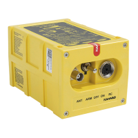
(3) ELT installation
• Check that the ELT identification label matches the aircraft tail number.
• If the mounting bracket is fitted with a Programming Dongle (P/N
S1820514-01), remove the Water Switch Sensor connector (if any) and
connect the programming dongle to the ELT.
CAUTION: DO NOT INSTALL THE ELT IN A LOCATION DIRECTLY
EXPOSED TO THE SUN.
• Perform a Self-test (see paragraph “SELF-TEST”).
• If test result is OK, switch back to “OFF”.
• Disconnect the Programming
Dongle (if applicable) and stow
it in the compartment designed
to this effect inside the bracket.
Ant Arm Off On
RC
An
t
Ar
m Of
f
O
n
RC
 Loading...