PAGE: 102
MAR 30/2020
INSTALLATION MANUAL OPERATION MANUAL
KANNAD 406 AF / AF-H / AF (6D)
© 2020 Orolia S.A.S. All rigths are strictly reserved.
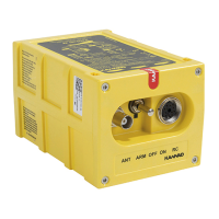
2. Controls
The following controls are to be found on the ELT front panel (from left to right):
1. 3-position switch ARM/OFF/ON;
2. Visual indicator (red);
3. DIN 12 connector for connection to Remote Control Panel
, CS144
int
erface module, dongle or programming equipment;
4. BNC connector for the antenna.
Figure 101: Front Panel
The visual indicator gives an indication on the working mode of the beacon:
• after the self test: a series of short flashes indicates an unsactifactory se
lf
t
est, one long flash indicates a correct self test;
• in operating mode: periodic flashes during 121.5 / 243 MHz transmission;
• long flash during 406 MHz transmission.
A buzzer gives audio information on the beacon working:
• continuous tone during self test;
• 1 beep every 0.7 second during 121.5 / 243 MHz transmission;
• silence during 406 MHz transmission.
CAUTION: WHEN ACTIONING THE ARM/OFF/ON SWITCH, PULL LEVER
TO UNLOCK AND SET TO POSITION.
 Loading...